CHDK (canon hackers development kit) is a temporary firmware hack that allows you to run custom code and commands on canon compact digital cameras. It is often used on high altitude balloon flights to run an intervalometer to take a photo every x number of seconds. The scripts are written in LUA or uBasic, with LUA seeming to be the preferred language. You can take this one step further and use CHDK it to log data such as CCD temperature like Mark Ireland (S_Mark) from Stratodean.
Now the above is pretty neat, but up until starting this project I really underestimated the power of a camera running CHDK! In the article below I will be using a Canon PowerShot A530 to broadcast photographs over a Radiometrix NTX2 FSK radio module, in a similar way Dave Akerman does on his Raspbbery Pi payloads.
SSDV (Slow Scan Digital Video) is a packetised digital form of SSTV (Slow Scan TeleVision). It can be used to transmit small images along with the regular telemetry transmitted by a payload during flight. Any digital mode that can carry text or data can be used, although the current implementation is limited to 8-bit RTTY (Radio TeleTYpe).
This is a vast improvement over simply sending the JPEG data as it supports forward error correction in the (likley) event that some bits are scrambled in the receiving process. It also supports integration into the UKHAS distributed listener platform, a group of enthusiasts who tune their HAM radios and SDR’s into balloons and upload the data to a central server.
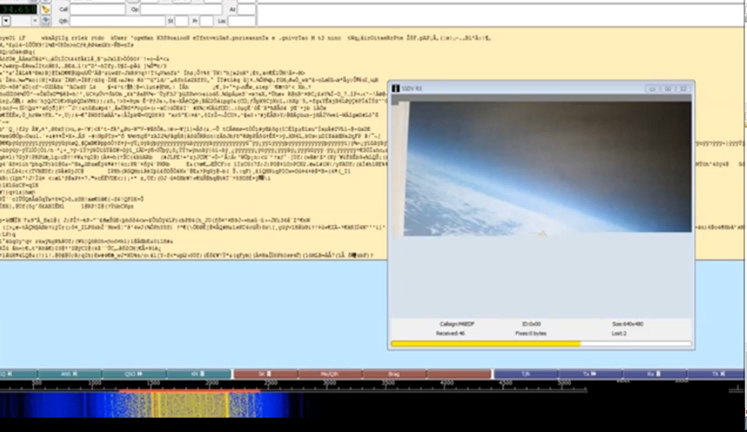
RTTY was originally used on teleprinters in the form of Baudot (5 bit). An RTTY transmitter broadcasts a continuous carrier which shifts up and down in frequency depending on the bit being sent. This produces the MARK (upper) and SPACE (lower) tones. You can see these two tones in the waterfall above). This is known as FSK (frequency shift keying). In this case we will not be using Baudot, instead we will be using 8 bit ASCII with one start and one stop bit to send a byte of SSDV data at a time.
On the CHDK wiki I started to read up on how toggling one of the cameras LEDs can be used to dump the firmware of a camera over serial. So I started off trying to produce RTTY by toggling an LED on and off. Whilst the code behind this worked, the timing was very inconsistent and I struggled to get anything above 33 bits per second. Not ideal for sending images! I figured there must be an alternative.
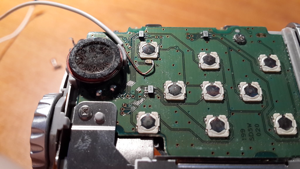
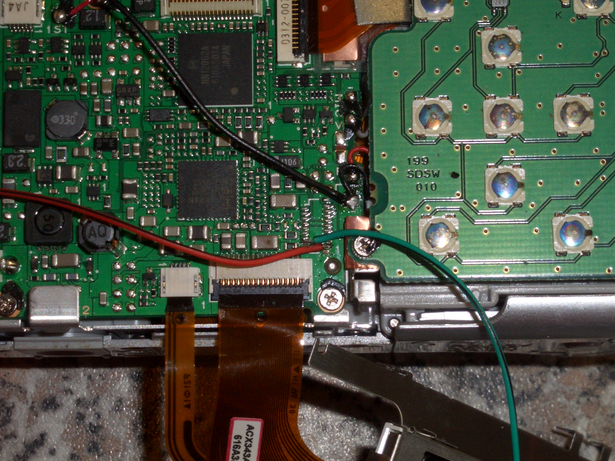
The camera has an ARM processor and runs VxWorks as an operating system, A popular OS for embedded devices ranging from mobile phones to the Mars Curiosity Rover. Using the cameras UART connections it is possible to access the VxWorks event shell and issue basic commands to the camera. The UART connections on the A530 are located under the display and require some fiddly soldering to the unpopulated chip footprint to connect! (Red wire below is the Tx) The UART’s default settings are 115200 baud 8N1.
Upon experimenting with the UART connected to PuTTY running on my PC, using a USB to TTL converter. I found that the Printf command seemed suitable for writing text to the port. The Printf command is a native call and must be registered by calling SystemEventInit in the VxWorks shell before using it.
To call a native VxWorks function from LUA you must enable native calls in the CHDK menu (ALT, menu, misc, enable lua native calls [check]). Commands can then be executed using event_proc as below.
call_event_proc(“SystemEventInit”)
call_event_proc(‘Printf’,’Script Started’)
To make the UART suitable for RTTY the baud rate will need to be dropped to something a little more sensible, in my testing both 50 baud and 600 baud worked well, however 300 baud seemed to drop characters. Reyalp on the CHDK wiki helped me out by showing me how ioctl() can be used to change the UART settings, and finding the memory addresses for it along with the function codes for some of the commands from VxWorks.
fd=call_func_ptr(0xffec8b34,”/tyCo/0″,0,0) –fptr_open (Opens the UART on fd)print(“fd:”,fd) –fd>0 if the UART was opened successfulystatus=call_func_ptr(0xffec8630,fd,4,600) –fptr_ioctl(4=FIOBAUDRATE,600=baud)status=call_func_ptr(0xffec8630,fd,3,0) –FIOSETOPTIONS,3=OPT_RAW,0=OFF (Stops VxWorks messing with null bytes and line returns)print(“status:”,status) –0 probably means successcall_func_ptr(0xffec84f0,fd) –Closes down fd
The 0xffec8630 function address points to ioctl on the a530, this will probably vary from camera to camera and can be found in stubs_entry.s for your camera in the CHDK source. The function codes for the various icotl commands in VxWorks can then be looked up here [backup: ioLib].
Initially I had a lot of trouble with VxWorks messing with some bytes I was sending to the UART, such as 0x00, and 0x0D being automatically followed by a 0x0A (need to check this). This can be overcome by setting the OPT_RAW option in FIOSETOPTIONS as above.
I found that printing a whole binary file in one go as a single string did not work, so I use a for loop to print each byte in a string to the UART, rtty being the string name to print below. (note in LUA strings start at character position 1)
for d=1,string.len(rtty),1 docall_event_proc(‘Printf’,’%c’,string.byte(rtty,d))end
Now from this point I could encode a JPEG image to SSDV using Phil Heron’s [fsphil] C based encoder running on a Linux PC. Copyy the files to the SD card,and then read them out to the UART and have dl-fldigi decode them perfectly. The next step is where the real fun started, compiling the C based SSDV encoder into the source of CHDK…
With some more advice from Reyalp at CHDK, Phil and I had a go at setting up the environment required to build CHDK, with myself working on Windows and Phil working on Linux. After a couple of days of Phil installing various bits of Linux software such as GCC, and myself trying to download one of the thousands of CHDK source trunks that would actually build, we managed to succeed at about the same time (For some reason the windows GUI decided to auto-update and started working from that point…). Phil had a go at implementing the C code from his SSDV encoder into the source and we had a semi-working encoder after just one evening! It took a few more revisions of the firmware as we tested different ways of calling the functions and addressing memory.
CHDK build with SSDV for a530 ONLY!
NOTE: I have built the firmware for every platform supported so to download a binary, scroll down…
You can use CHDK-Shell GUI under windows to compile the patched trunk for your camera. Or if you are a Linux super genius you can build it using GCC. For windows head to the page linked above. Read it ALL! Download the latest FULL program, run it, enable online mode, let it update, restart. Keep doing the above and eventually you will be up to date enough for it to automatically download the most up to date trunk for you to use.
Change the trunk in CHDK_Shell GUI to the trunk we just patched: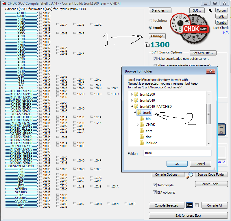
CHDK_Shell should restart and you can tick off your cameras firmware on the list then click “compile selected”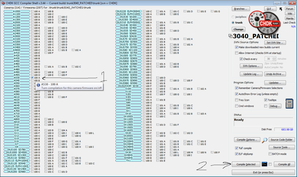
Unzip the binaries found in chdk\trunk\trunk3040_PATCHED\trunk\bin (or wherever) to your SD card and boot CHDK, its that easy!
I have had a go at building for every platform available so if you are feeling lazy, give one of these a go. TRUNK3039_SSDV BINARIES DOWNLOAD (Thanks to Dom for hosting the files!)
The first step to encode a JPEG image from LUA is to open the file and read it into memory (JPEG string).
fh=io.open(“A/DCIM/101CANON/filename.jpg”)
jpeg=fh:read(‘*all’)
fh:close()
We now have to create a new encoder object which we can feed the JPEG file into (specifying the callsign as CALL and imageID as 0).
s = ssdvenc.new(“CALL”, 0)
Now we feed the JPEG file (held in the variable we set earlier) into our SSDV encoder object above.
ssdvenc.feed(s,jpeg)
Now we need to enter a loop to make the object encode each packet, checking if the encoding is complete each time so we can jump out of the loop.
i=1 –packet encoder counter
rtty = “” –initialize output string
repeat –start loop
print(“Packet “,i,” encoding”)–print encoder status message to screen
r, packet = ssdvenc.read(s)–Read the output packet from the encoder, r being encoder status and packet being 1 SSDV packet.
if r == SSDV_OK then
–If we have data, then do something with it
rtty = rtty .. packet –concatenate new packet onto the end of output stream
i=i+1 –increment packet counter
end
until r ~= SSDV_OK –keep trying to get new packets until the encoder reaches EOF
ssdvenc.close(s) –Close the encoder
So now we have SSDV data in the rtty string. All we have to do is loop through each byte in the string and print it out the the UART
for d=1,string.len(rtty),1 do –loop through each byte
call_event_proc(‘Printf’,’%c’,string.byte(rtty,d))–print byte to UART as a byte
end
You *should* now have 600 baud SSDV flowing out of your hardware uart and into your ntx2. With a suitable voltage divider you can set the shift to 600Hz and have this decoding in dl-fldigi and uploading to the web!
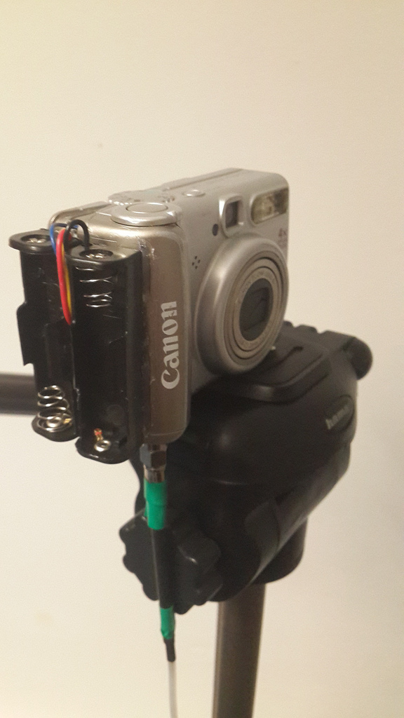
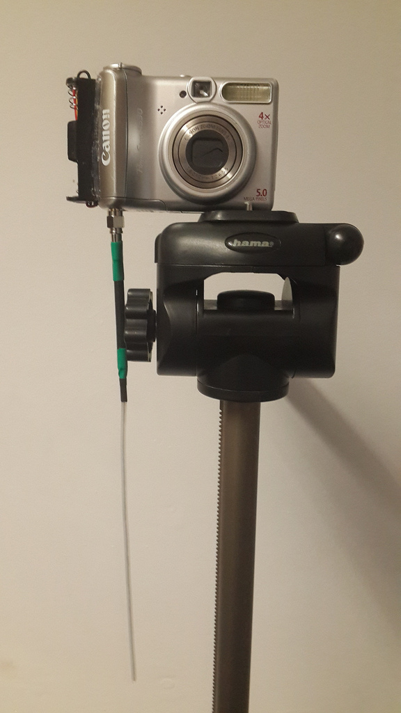
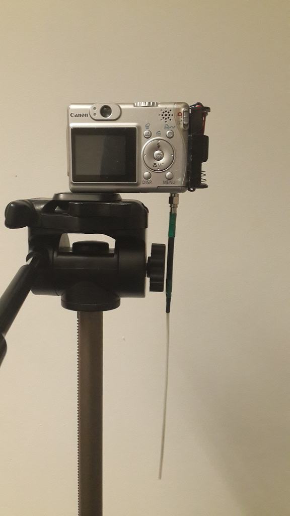
Whilst Phil was compiling the new source, I worked on integrating the transmitter into the camera. The battery bay worked out to be the perfect size, with space for an SMA connector in the battery door!
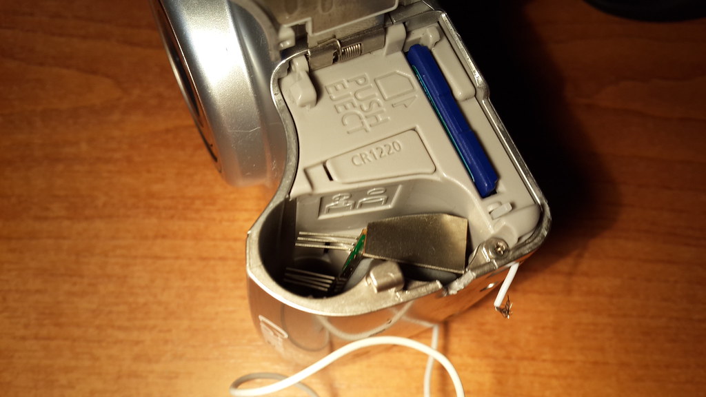
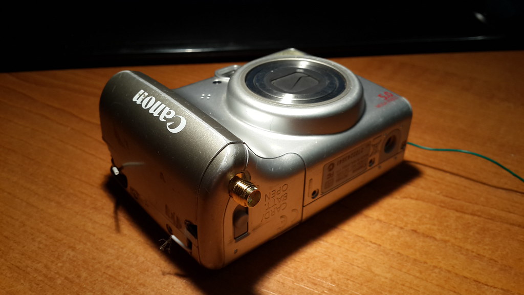
The now out of action battery bay is not a problem, as I wanted to build a 4 cell battery holder to power the camera anyway. This will probably be a 3d printed addition to snap on to the back of the camera or on to the side. As I wanted to demo this at the UKHAS 2013 conference I have added 2 AA holders to the side of the camera just with hot glue for power.
Demo video of the camera in testing.
People have showed a lot of interest in the project and with a few more tweaks to the code I will be ready to launch it in the next couple of months!
The only thing preventing the camera becoming an entire self contained tracker is the lack of positioning data. I am hoping to be able to get hold of a new canon camera with GPS for geo tagging and send back position reports. I very much doubt canon will have used any specialist GPS chips in the camera to allow it to work above 12km (to comply with US regulations that prevent you using a commercial GPS to build your own cruise missile). I guess the only way to find out is to rip one open! Chances are that whatever GPS module they have used will output serial NMEA data, so a uBlox chip (works to 50km) could quite easily be patched in.
Stay tuned for updates!

Pingback: Digital camera becomes video transmitter
Pingback: Digital camera becomes video transmitter - RaspberryPiBoards
Pingback: rndm(mod) » Digital camera becomes video transmitter
Pingback: Digital camera becomes video transmitter — Blog of MPRosa
Pingback: Cámara digital se convierte en transmisor de vídeo - | Indagadores |Seguridad informatica |Seguridad en internet
I am just amazed. Thank you SO MUCH for doing this, and then taking the time to also explain it in detail. I so very much wanted to do a HAB project with my children (more for the experience than the results) and eventually abandoned the idea when we all discovered that we had bitten off a little more than we could chew in the tech/electronics areas. This article really helps people like myself gain some perspective on what is available. I can think of at least a half dozen projects where something of this nature would be ideal. Now I just need to find some FSK / RTTY resources to start to understand the entire HAM lingo. Thank you again, and best wishes to you for this useful and inspiring endeavour.
Hi! Glad you found it interesting. If you would like some more info on high altitude ballooning in general check out the UK High Altitude Society Wiki (ukhas.org.uk).
Chris
Hi Chris!
This is fantastic – just thinking that you should be able to at least _receive_ GPS data from a Ublox breakout because you still have your UART Rx free. The issue would be putting the Ublox into high altitude mode. However, I recently bought an Adafruit GPS and it had the high -altitude firmware. Haven’t tested it in anger yet, but it could be that they will work to 50km without needing any setup, so you could just hook one up to your open Rx and read the default data (GPMRC is included in the default, which would probably be enough).
You are welcome to borrow the Adafruit module if you want to try it out.
Ugi
Hi Ugi, thanks for the comment!
From what I understand reading from the uart buffer is somewhat more difficult than writing to it as it is all controlled by the OS.
I will have to have a play with opening and reading over the weekend..
Chris
Pingback: Hack: A Canon PowerShot A530 with CHDK Used to Shot (and send) Pictures from Stratosphere | CanonWatch CanonWatch
Hi Chris,
woow! amazing! I’m preparing things for my 1st launch and this is exactly what I was dreaming abt – simple and all in one, thanks for great job!
Cheers!
Serge
Very nice project! What hardware/software do you use to decode the SSDV? An RTL-SDR dongle?
Thanks! I have been using my yaesu ft-817 to receive.
I have not yet tested with my SDR, you probably wont get brilliant range from it but it should work for testing.