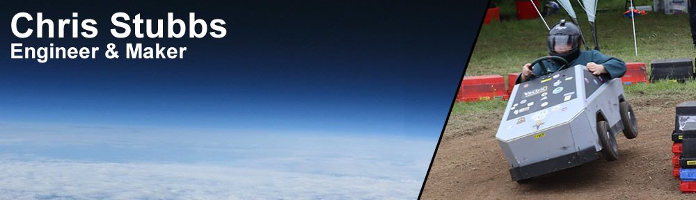
VOLT-CRANE-O – Hacky Racer Build Log

[This page is auto populated from the Hacky Racers Wiki]


Volt-Crane-O
Voltcraneo racing.JPG
Built By Chris Stubbs
Theme Liebherr Mobile Crane
First Race EMF 2024
Current Status Active
Motor 6x Hoverboard 6.5″ Hub Motors
ESC 3x Hoverboard PCB
Battery 48V 12S3P Li-Ion/LiPo (2x 6S)
Gearbox Direct hub motor
Contact @emfroamer
View all Racer Profiles


Background

Ltm1060.png

Volt-Crane-O is a scratch built, 6 wheel drive, 4 wheel steer, fully functional miniature crane.

The theme is based around a Liebherr 6 wheel mobile crane.

Construction

The chassis is constructed from wood, mostly 2x4. Fixings are mostly wood screws, except the use of M6/M8 bolts where additional strength or rules compliance is needed (bumpers).

The body is also constructed from a lightweight wooden frame, panelled with thin plywood.

Steering uses two M8 threaded tie rods to connect the pitman arm to the trailing spindle arms. The steering column is 25mm bed frame offcut with socket set articulating joint. There is a second pitman arm on the steering column at 90 degrees to produce a back and forth steering linkage to the rear axle, which is then translated 90 degrees again using a pivot to drive the rear tie rods. The steering angle of the rear axle is approximately 1/3rd of the front steering angle, because the rear/mid wheelbase is approximately 1/3 the front/mid wheelbase. No real thoughts were given to steering geometry and the handling is somehow "fine".

The steering components are mostly constructed from offcuts of bedframe, steel angle welded to make U section, or 4x30mm flat steel bar.

Wooden chassis with steering rear view
Wooden chassis with steering front view
Steering components

Powertrain

Volt-Crane-O utilises 6x 6.5″ 350W hoverboard motors, fitted with 4.10/3.50-5 tyres. Regenerative braking is extremely effective if configured correctly, however one motor has been fitted with a mechanical brake from a Xiaomi M365 scooter to comply with the rules.

Power is delivered to the motors using 3x original hoverboard PCBs running a fork of EFeru’s FOC firmware (links at the bottom). A higher current limit is applied to the rear motors to aid traction given the awful weight distribution. Throttle is applied in torque mode, controlled from aliexpress hall effect pedals via an Arduino.

Traction power is supplied by either 2x custom 6S3P Samsung 30T 21700 Li-Ion battery packs, producing 48V total. Each pack contains a 60A DALY BMS, or 2X 6S 9500mAH CHNL Lipos. Another 6S4P Li-Ion set using reclaimed hoverboard 18650’s also exists for testing and running around, but does not perform well enough for racing.


Other Features

The crane boom can be raised and lowered, extended and retracted (2 sections), and the winch/hook raised and lowered by a control panel below the steering wheel.

The boom itself is constructed from 3 telescopic sections of 18mm plywood, running on internal/external 608 skateboard bearings or homemade tubular bearings at each end.

The winch is a 12V caravan/boat trailer winch rated for 900kg.

All other actuation is driven by drill motors with their attached two speed (low gear) gearbox and chuck, which drives an M12 nut along a threaded rod. Opposing bearings are used to take the axial forces rather than relying on the drill. The boom raise/lower rod drives a nut attached to the elbow of an old monitor mount, which in turn raises the boom.

Power is provided by a dedicated 3S lipo.

The boom is lowered in to a cradle and secured directly to the chassis using the steel cable during racing. It fits within the envolope of the body/bumpers.

10 strobing orange hazard lights, 6 orange chasing LED beacons, 2 white headlights and 2 red brake lights illuminate the track for night racing.

An Arduino logs all hoverboard and control telemetry locally via SD card.

Boom extended
Boom extension motor
Boom lift motor

Awards

  • EMF 2024
    • 3rd place overall.
    • 1st place Moxie.

BOM

coming soon

Limitations

Steering wheel snapped off.

Sluggish on mud/grass.

Heavy (100kg).

Happily pops 30A fuse if accelerating too hard/long.

Resources

Twitter Account @EmfFRoamer

The Hoverboard firmware, Arduino code, and CAD on GitHub

Remote control Pi code on GitHub

Chris’ website


For the latest news, posts and discussions about everything Hacky Racers, head over to the Facebook group.

CYBR TRK – Hacky Racer Build Log

[This page is auto populated from the Hacky Racers Wiki]


CYBR TRK
Cybr trk profile.jpg
Built By Chris Stubbs and Dom Tag
Theme Tesla Cybertruck
First Race EMF 2022
Current Status Active
Motor 4x Hoverboard 6.5″ Hub Motors
ESC 2x Hoverboard PCB
Battery 48V 12S3P Li-Ion (2x 6S)
Gearbox Direct hub motor
Contact @emfroamer
View all Racer Profiles


Background

Cybr trk rgb.jpeg

CYBR TRK started life in 2022 as the EMF Roamer; a publicly controlled, raspberry pi powered robot, that could roam the EMF site. This was a follow on project from the much smaller EMF Roamer in 2018. One of the main objectives was to also be as Hacky Racers legal as practical.

The theme is a loose caricature of the Tesla Cybertruck, rather than an original donor vehicle.

Interview

Construction

The chassis is constructed from wood, mostly decking frame offcuts, utilising recycled hoverboard components wherever possible. The front wheels are able to articulate using a hoverboard casting as a joint, in a crude suspension to keep 4 wheels on the ground.

The body is also constructed from a lightweight wooden frame, panelled with thin plywood. This is removable from the chassis to enable maintenance and transport.

Steering uses two M8 threaded tie rods to connect the pitman arm to the leading spindle arm. The steering column is 25mm electrical conduit with socket set couplings. No real thoughts were given to steering geometry (bad) as this was a retrofit from the fly-by-wire servo system.

Wooden chassis
Wooden body
Steering components

Powertrain

CYBR TRK utilises 4x 6.5″ 350W hoverboard motors, fitted with 4.10/3.50-5 tyres. Regenerative braking is extremely effective if configured correctly, however one motor has been fitted with a mechanical brake from a Xiaomi M365 scooter to comply with the rules.

Power is delivered to the motors using 2x original hoverboard PCBs running a fork of EFeru’s FOC firmware (links at the bottom). A higher current limit is applied to the rear motors to aid traction given the awful weight distribution. Throttle is applied in torque mode, controlled from a playstation racing pedals set via an Arduino.

Traction power is supplied by 2x custom 6S3P Samsung 30T 21700 Li-Ion battery packs, producing 48V total. Each pack contains a 40A continuous rated BMS. A second 6S4P set using reclaimed hoverboard 18650’s also exists for testing and running around, but does not perform well enough for racing. Block diagram of electrical configuration as configured for EMF Camp (local & remote mode)

Electrical block diagram

Other Features

Cybr trk trailer.jpg

A fold up trolley makes an effective trailer for running gear from the car park to the track!

Originally the car contained over 300 individually addressable RGB LEDs. It could produce an impressive RGB underglow, front headlight bar, and rear brake bar with animated indicators. This number has however declined as they were damaged in races and modifications.

When deployed as the EMF Roamer, the vehicle could be controlled by anyone using a web browser. This used a websockets connection for control, and jsmpeg for live video. A presentation was given at EMF with more information, but recordings could not be published. Presentation without audio available here.

Cybertruckservo.jpg

A windscreen wiper motor was originally used as a steering actuator with a pot for feedback, all hooked up to an arduino PID controller. The setpoint could then either be fed from the steering wheel (an old playstation controller), or the Pi for remote control. Using the arduino also allowed current limiting and fault detection, to prevent fire if it gets jammed. Turns out as a neat trick, you can run a PID loop to control the servo angle, and a PID loop to control the max current, and just take the minimum output from either controller as the PWM drive! This was eventually removed in place of basic mechanical steering, at the request of Hacky Racers on safety and legality basis.

The Pi logs all hoverboard and arduino telemetry locally via MQTT/NodeRed/Grafana.

Awards

  • Fully Charged Live 2023
    • 1st place overall.
    • 2nd place race position.
    • 2nd place on Moxie points.
  • EMF Camp 2022
    • Beat slowest ever hacky racers lap (previously held by EMF Roamer in 2018)

BOM

Item Cost Total
Tyres £103.25 £371.15
Wood for frame/body £40.00
Control PCB £32.00
Swegway 1 £30.00
Swegway 2 £30.00
Chassis alu £20.00
Motor drive enclosures £18.96
Light bar £12.45
Paint £10.00
Bumper steel £10.00
Wire £10.00
Rod ends £9.31
Chair £8.00
Pedals £7.86
LED strip £5.60
Steering Wheel £5.00
12V reg £4.89
Steering brackets £4.46
Steering bolts £3.32
Steering column £3.25
Steering rod £2.80
Battery box Excluded
Brake kit Excluded
Brake standoffs Excluded
Kill switch Excluded
Bumpers Excluded
Batteries Excluded
Fuse Excluded

Limitations

Tips over a lot.

BMS’s run extremely hot.

Happily pops 30A fuse if accelerating too hard/long.

Resources

Twitter Account @EmfFRoamer

The Hoverboard firmware, Arduino code, and CAD on GitHub

Remote control Pi code on GitHub

Chris’ website


For the latest news, posts and discussions about everything Hacky Racers, head over to the Facebook group.

Building a Queue for the EMF Roamer with the Vonage SMS API and PHP

If you haven’t heard of Electromagnetic Field (EMF) Camp, imagine a field in the quaint English countryside, temporarily populated by 2,500 curious tech/maker enthusiasts; fiber internet, radio masts, robotic bartenders, lasers illuminating the sky, and wild/wacky inventions as far as the eye can see.

One of these wacky inventions was the EMF Roamer, a quarter-scale wooden Tesla Cybertruck, deployed to roam around the side, controlled by anyone over the internet!

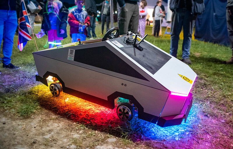
Just allowing people to drive it line of sight wasn’t good enough! Especially not in the world of the Internet of Things. Live video from a camera, along with the location on a map is streamed to the user while they have control of the roamer.

A free for all in terms of control would have been a mess, so we devised a queue system. People could join the queue in their web browser and wait their turn, or provide a mobile phone number to receive an SMS when their turn is up (thanks Vonage!). The queue system is “serverless”, in that it does not require a dedicated server. Instead, it runs on simple shared hosting, with PHP coordinating the queue on-demand, which is stored in a MySQL database.

To build a queue system for yourself, take a look at the WebUserQueue project on my GitHub, or follow the guide on the Vonage Developer Blog.