[This page is auto populated from the Hacky Racers Wiki]
VOLT-CRANE-O – Hacky Racer Build Log
Reply

[This page is auto populated from the Hacky Racers Wiki]
[This page is auto populated from the Hacky Racers Wiki]
If you haven’t heard of Electromagnetic Field (EMF) Camp, imagine a field in the quaint English countryside, temporarily populated by 2,500 curious tech/maker enthusiasts; fiber internet, radio masts, robotic bartenders, lasers illuminating the sky, and wild/wacky inventions as far as the eye can see.
One of these wacky inventions was the EMF Roamer, a quarter-scale wooden Tesla Cybertruck, deployed to roam around the side, controlled by anyone over the internet!
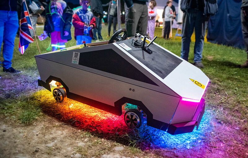
Just allowing people to drive it line of sight wasn’t good enough! Especially not in the world of the Internet of Things. Live video from a camera, along with the location on a map is streamed to the user while they have control of the roamer.
A free for all in terms of control would have been a mess, so we devised a queue system. People could join the queue in their web browser and wait their turn, or provide a mobile phone number to receive an SMS when their turn is up (thanks Vonage!). The queue system is “serverless”, in that it does not require a dedicated server. Instead, it runs on simple shared hosting, with PHP coordinating the queue on-demand, which is stored in a MySQL database.
To build a queue system for yourself, take a look at the WebUserQueue project on my GitHub, or follow the guide on the Vonage Developer Blog.
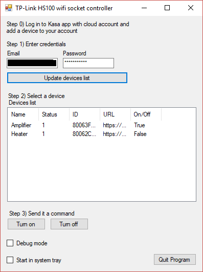
I own a couple of TP-Link HS100 WiFi sockets.
When I’m using my PC, it’s a minor pain to have to unlock my phone, open the Kasa app, wait for it to finish displaying the infernal splashscreen, then turn on my socket.
What I wanted was a program sitting in the windows tray to control them. So that’s what I made. It’s in VB.NET. All you need to do is toggle a switch icon on your taskbar.
This is heavily based on the API research over at itnerd.space

Instructions:
Changelog:
1.0.0.4 – 15/05/2018 – Fix errors when a device in your account is offline.
2.0.0.0 – 23/06/2019 – New features: CLI mode. Copy ID to clipboard. Bug fixes: Better management of tray icons. Removed from alt-tab list when minimised to tray.
2.1.0.0 – 25/06/2019 – New features: Start with Windows. Create on/off timers for devices. Automatically turn devices on/off on program launch/exit.
Download source code from GitHub.
[GUIDE] Make windows taskbar always show an icon
[GUIDE] Command line interface
This program has no affiliation with itnerd.space or tp-link. I accept no liability for its use. This program is provided without warranty/guarantee.
Since the UKHAS conference in August I have been playing with some UKHASnet nodes, which are “A simple wireless network aimed for use with low power licence exempt wireless modules”.
The system was developed by members of the UKHAS community, but is not specifically aimed at ballooning (however can be used for it).
I have 2 LPC810 based nodes designed by James Coxon, and an AVR node from Phil Crump. After I had these set up, I loaded Phil’s code onto an old Cheapo v3 PCB and bug soldered a RFM69 onto the back. This made a pretty effective GPS node and after some tinkering I had positions being uploaded to ukhas.net.
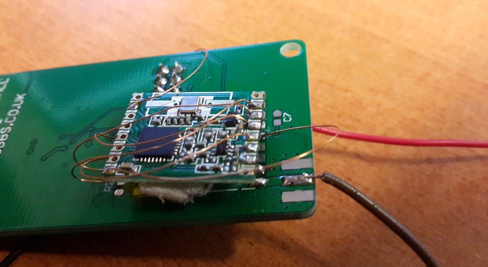
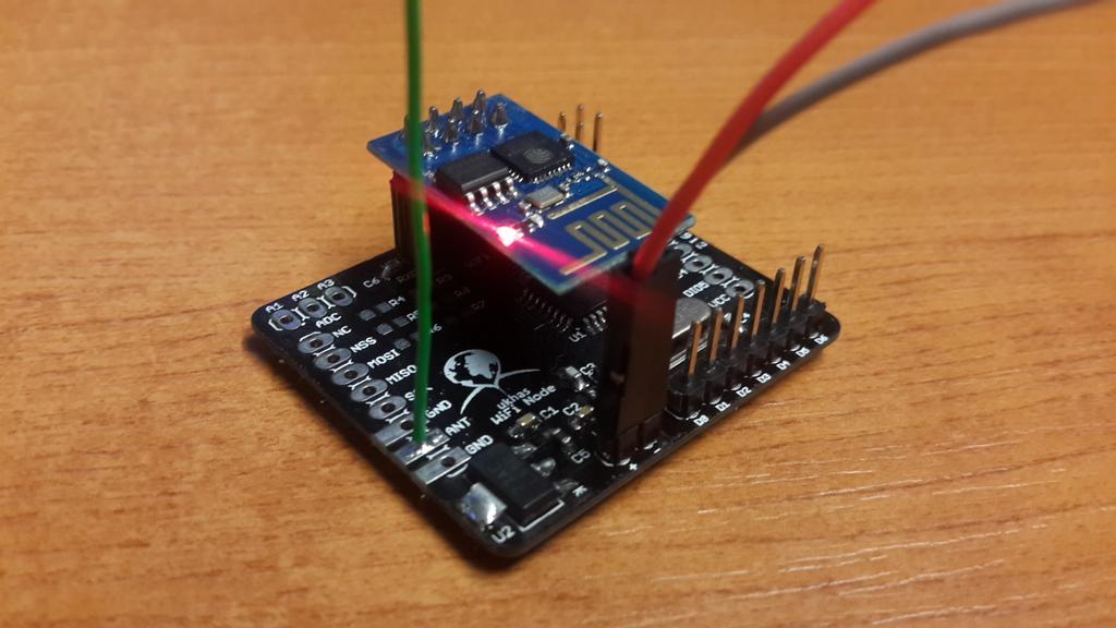
The system relies on packets being repeated between nodes, before hitting a “gateway” node which is connected to the internet. This may be a node connected to a PC, or a raspberry pi with an RFM69 radio. After seeing the ESP8266 popping up in various places, I decided to order a couple of modules and design a PCB for a simple AVR based wifi node.
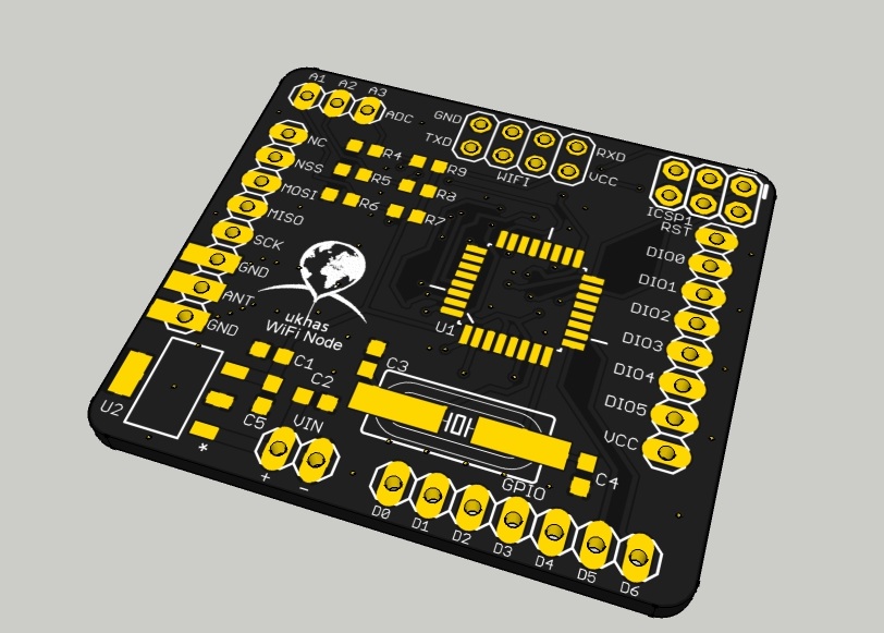
The PCB was very quick to put together and Phil’s repeater code had it working almost straight away.
I put together a library for sending HTTP POST requests to the ukhasnet server from an ESP8266 via AT commands. I updated my ESP chip with this firmware (File:V0.9.2.2_AT_Firmware.bin.zip from http://www.electrodragon.com/w/Wi07c / Mirror) to reduce the speed down to 9600 baud. The chip does indeed work with WPA2 (which I was not expecting, possibly down to the firmware update)
The node has been running now for about 72 hours with no apparent problems 🙂
The ESP8266 Library, repeater/gateway code (credit to Phil) and PCB files are up at https://github.com/chrisstubbs93/ESP8266
The basic upload sketch looks something like this:
#include "ESP8266.h"
#include "wifiConfig.h" //this is where you need to set your SSID and Password
#define DST_IP "212.71.255.157" //ukhas.net 212.71.255.157
#define WIFI_EN 7 //CH_PD

ESP8266 esp8266 = ESP8266();

void setup()
{
  Serial.begin(9600); //Open serial communications
  esp8266.initialise(Serial, WIFI_EN); //Pass it over to the ESP8266 class, along with the pin number to enable the module (CH_PD)
  while (!esp8266.resetModule()); //reset module until it is ready
  esp8266.tryConnectWifi(SSID, PASS);//connect to the wifi
  esp8266.singleConnectionMode(); //set the single connection mode
}

void loop()
{
  esp8266.uploadPacket(DST_IP, "your_data");
  delay(10000);
}
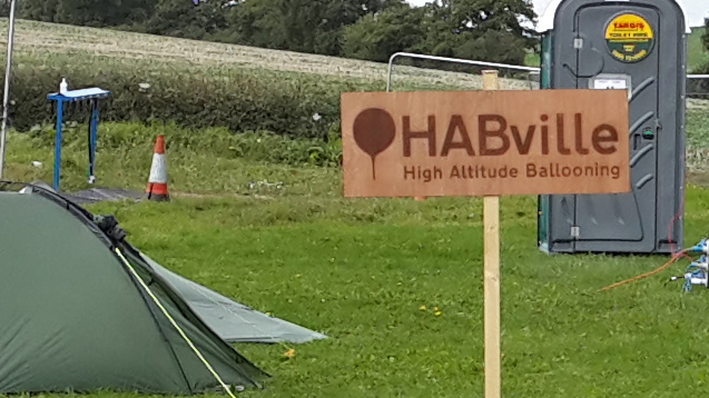
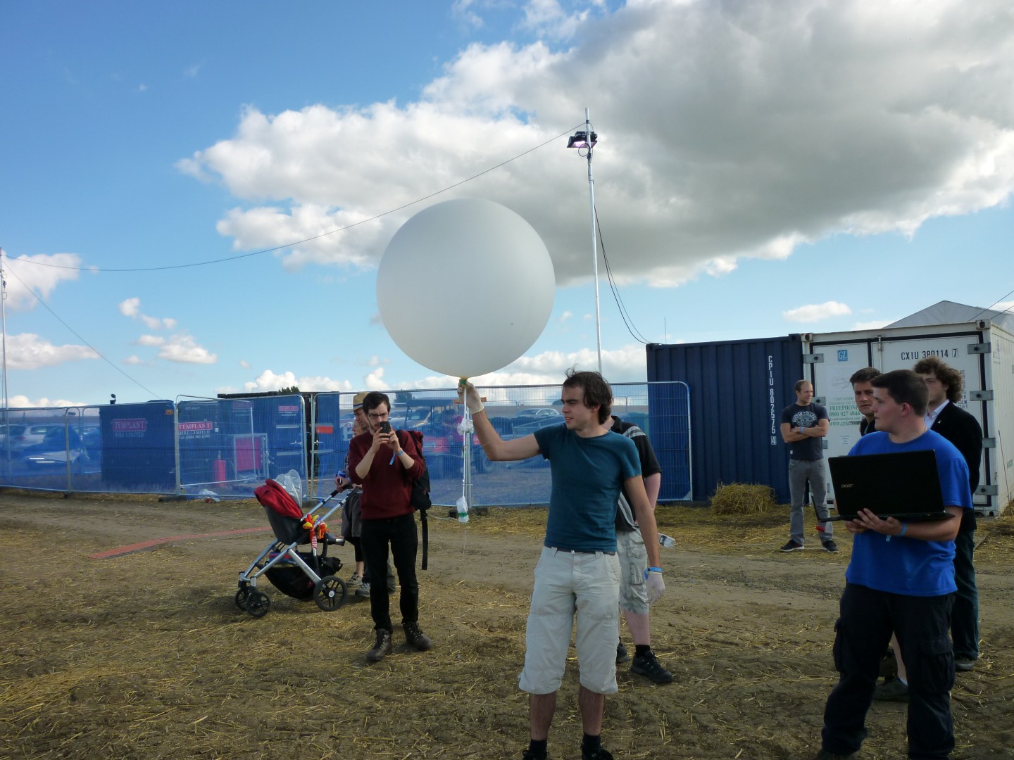
On the 29th August – 1st September, I joined over 1000 other campers at Electromagnetic Field camp in Milton Keynes. Said field was equipped with mains power and high speed internet, which allowed them to host some great workshops, talks and demos including on site laser cutting! I camped with a few other UKHAS members in our “villiage” aptly named “HABVille”
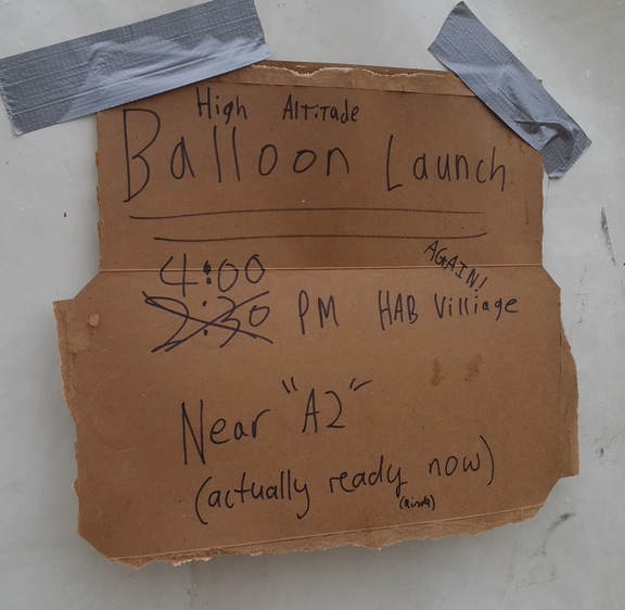
We ran a couple of launches, which had a pretty good turn out of interested people who arrived on time to watch. However with tradition the launches were vastly delayed as trackers were still being assembled and programmed.
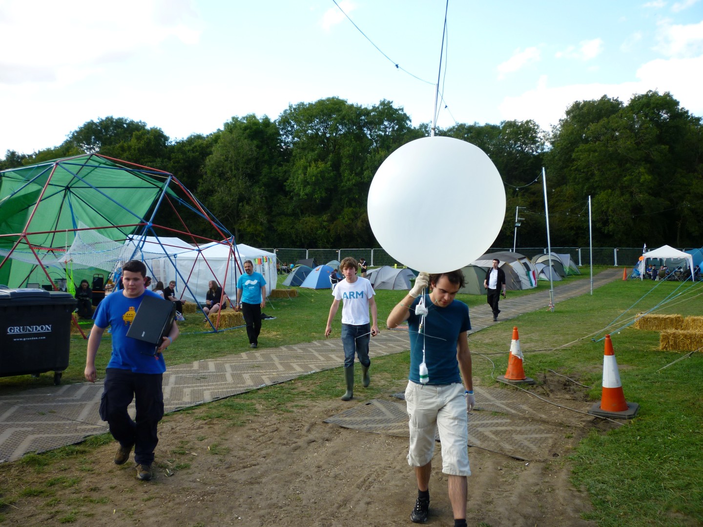
The first of these was one of my Cheapo boards on a foil balloon, which sadly didn’t quite manage to enter a float, but did cross the channel. The second was a JOEY board running both Matt’s TurboHAB and RTTY, a UKHASnet node, and Richard’s Bristol University SEDS tracker. All 3 of these payloads were carefully strung under a 100g balloon and filled with all the helium we could get our hands on.

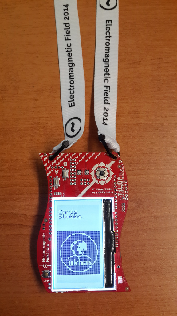
One of the other perks of the camp were the badges, which unfortunately weren’t quite ready to hand out as soon as the gates opened. The radio network for delivering weather and schedule updates (an awesome idea) was pretty ropey too. But provided some excitement when someones badge started working on it.
We also spent a bit of time down at The Grid, an interactive light installation put together by Adam Greig and David Turner. Which attracted a lot of attention when it sprung to life at night, with people drunkenly charging around in amazement as the poles lit up around them. Adam and David clearly put an awful lot of work into this project, which they discussed in their talk. I shot some footage on my unfortunately gimbal-less hex.
NottingHack brought along their BarBot, which happily served me an interesting concoction of alcohol.
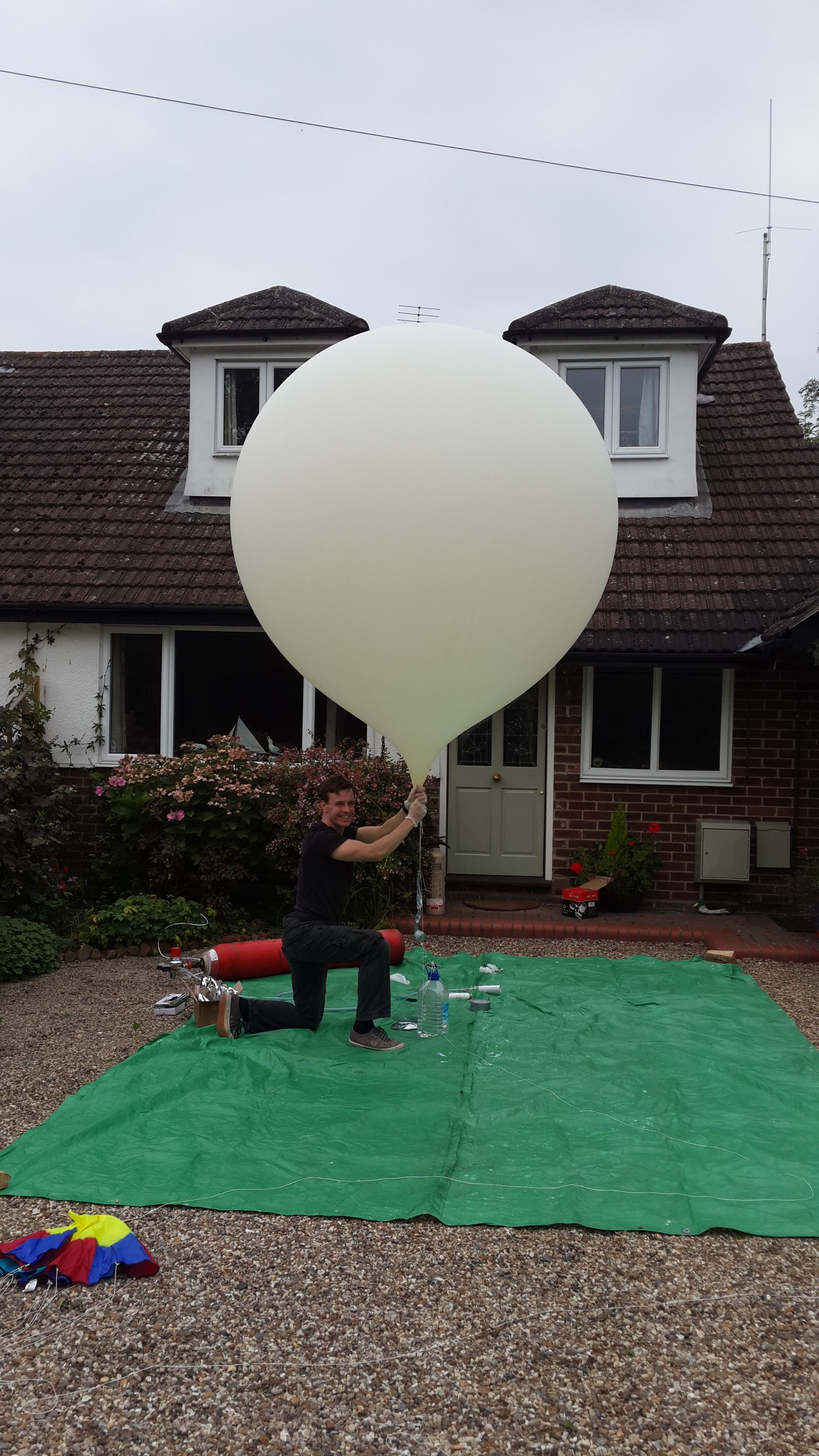
A couple of weeks ago I launched a few projects I had been working on over the last year or so on a 1200g Pawan latex balloon. These projects included:
The CHDK rig from the conference last year, sending live 600 baud SSDV images encoded straight on the camera. A Navspark based tracker. And A Cheapo Mini flying backup.
I did plan to launch a nasty looking GPS UKHASnet node, but the AVR got stubborn just as we were about to launch and refused to accept any new code.
The launch went off pretty much without a hitch and roughly on schedule, with some much appreciated help from Lewis.
Launch video to be added at some point..
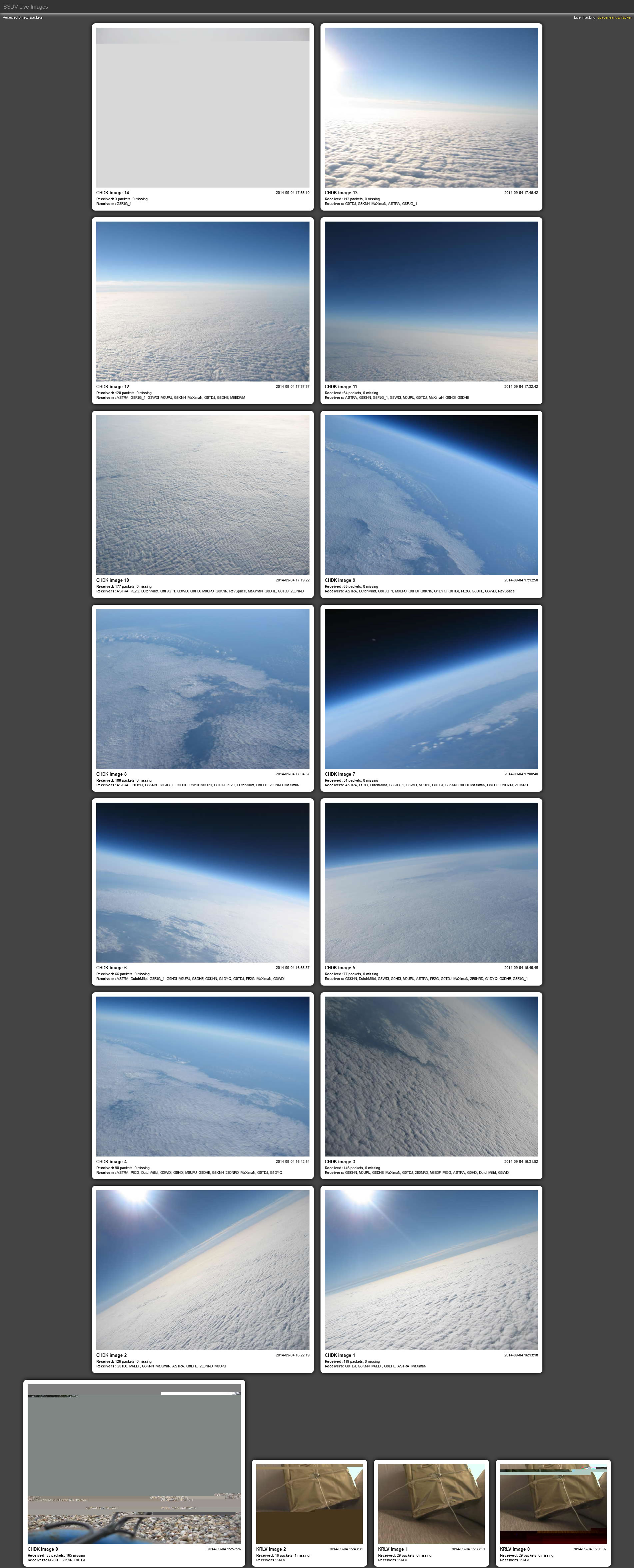
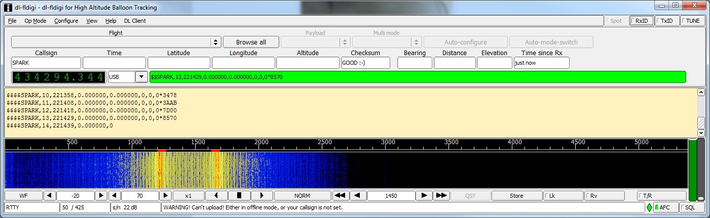
Things seemed to be going according to plan, until SPARK hit about 19KM and decided it had enough. The altitude stopped ascending and the GPS wandered off course, shortly followed by the GLONASS satellites dropping down to 0 and GPS to 3. I posted my results to the navspark forum, but their only theory was that it couldn’t handle the temperature. I’m not exactly sold on this, as it seemed to die at exactly 19km (hey, that could be a coincidence) and the board should feature a TCXO. Perhaps some modes need changing. I will repeat this experiment sooner or later.
Just as the flight started to get interesting, cheapo also decided today was not a good day for HAB. The battery voltage plummeted as the temperature dropped and silence fell. Luckily on the descent things started to warm up, increasing the battery voltage and bringing the tracker back in time to track the landing. I have not seen a lithium battery drop quite this much in voltage before, so I suspect I had a bad cell.
Surprisingly the part I thought most likely to fail actually performed perfectly! The camera sent down SSDV images throughout its flight, with no packets being missed! A great success and a final thank you to Reyalp from CHDK and Phil Heron for their help with the project. The next step will be to implement the whole thing again on a more modern camera with GPS, but I think a well earned break is due first!
The flight photos will appear here at some point, along with the 15gb of gopro footage…
The NavSpark was an indiegogo campaign launched some time last year. It is essentially a GPS receiver with a 100MHz processor and 1024kb of flash memory. It also allows you to compile and upload code for it straight from the Arduino IDE. It comes in at a price of around 15 USD and a similar form factor to that of the Arduino Nano.
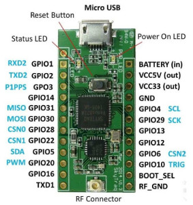
NavSpark board pinout.
After many months of waiting and a few badly translated Chinese update emails, my two preorder NavSpark boards arrived! They sat around on my desk for a fair few weeks before I decided to sit down and crack on with turning them into trackers.
The first step was to set one up on some breadboard with an NTX2B and a resistor network to set the shift, then toggle a GPIO pin on and off to produce the mark/space tones required for RTTY.
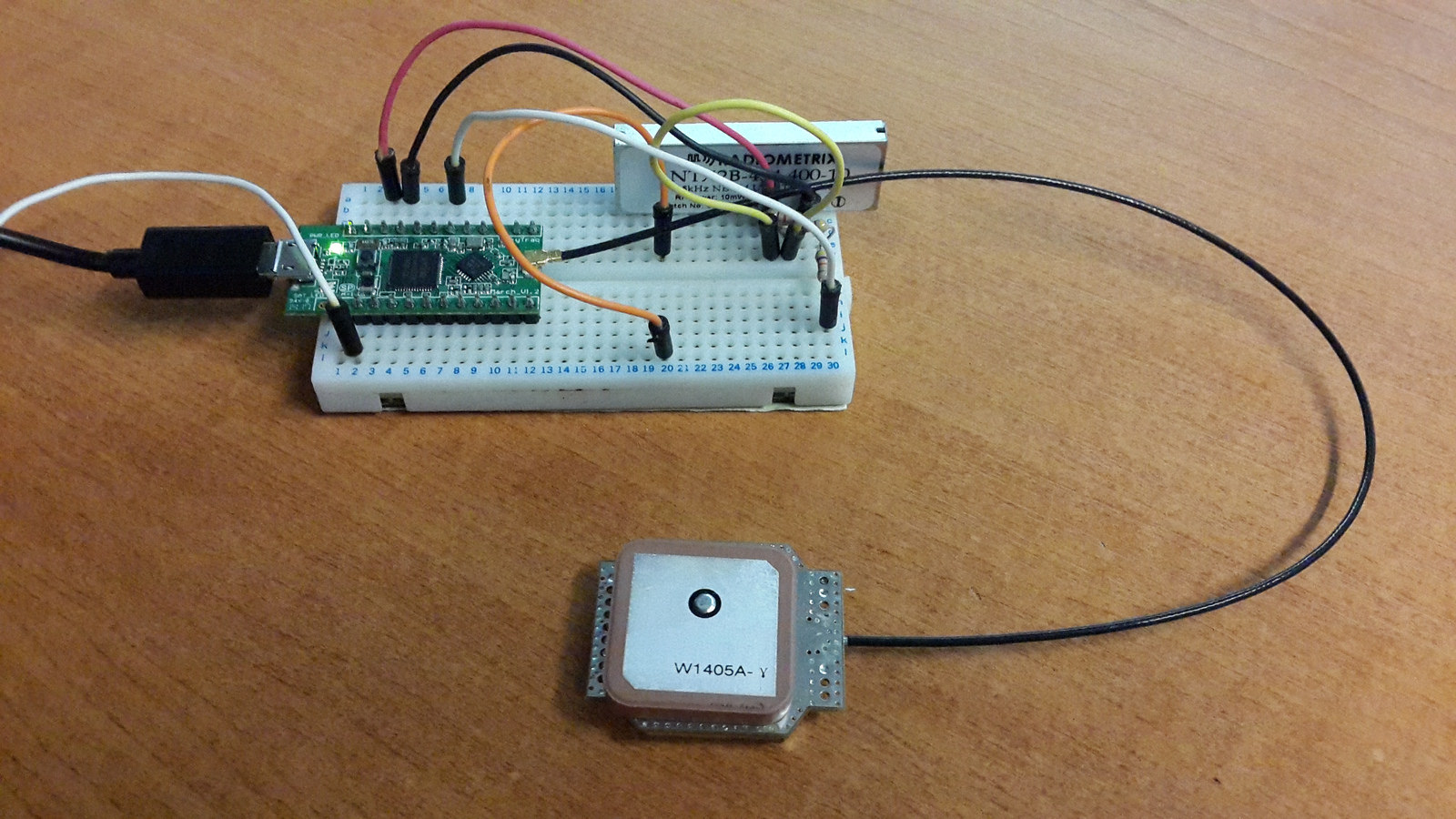
NavSpark board and NTX2B on breadboard
It took a bit of faffing around to actually get code onto it. Sometimes it will not allow you to upload, and you have to short BOOT_SEL to GND to restore the working bootloader from ROM, then try again. But I eventually had a program that was toggling pin 12 on and off.
Putting “GnssConf.init();” in “setup()” initializes the GNSS receiver and causes “task_called_after_GNSS_update()” to run. Inside this function its remarkably easy to get all the GPS data your tracker might want, without the need to mess around with any NMEA parsing.
void task_called_after_GNSS_update(void)
{
GnssInfo.update();
gps_hour = GnssInfo.time.hour();
gps_min = GnssInfo.time.minute();
gps_sec = GnssInfo.time.second();lat = GnssInfo.location.latitude();
lng = GnssInfo.location.longitude();alt = GnssInfo.altitude.meters();
gps_sats = GnssInfo.satellites.numGPSInUse(NULL);
gln_sats = GnssInfo.satellites.numGLNInUse(NULL);}
Then came the challenge to tackle the timing of sending RTTY. Luckily it turns out the Navspark has a few timers to use with millisecond precision [page 80 TIMER]
uint8_t tmr0 = Timer0.every(20, tmr_task);
Its then as simple as sticking Anthony Stirk’s great little Interrupt based RTTY script inside the tmr_task() function. With some minimal modification to write the GPIO pin high/low.
Check out the code here.
I soldered a couple of 4k2 0603 resistors between VCC and DATA, then DATA and GND on the NTX2, also shorting VCC and EN. I then soldered a 47K and 10K resistor in series to the DATA pin, then connected the other end to our NavSpark’s GPIO pin. You can solder the NavSpark board pretty much straight on top of the NTX2B, but its probably a good idea to add some insulation (kapton tape) between the two. The NTX2 GND is connected to the GND on the board, and VCC to the 3.3v regulated output.
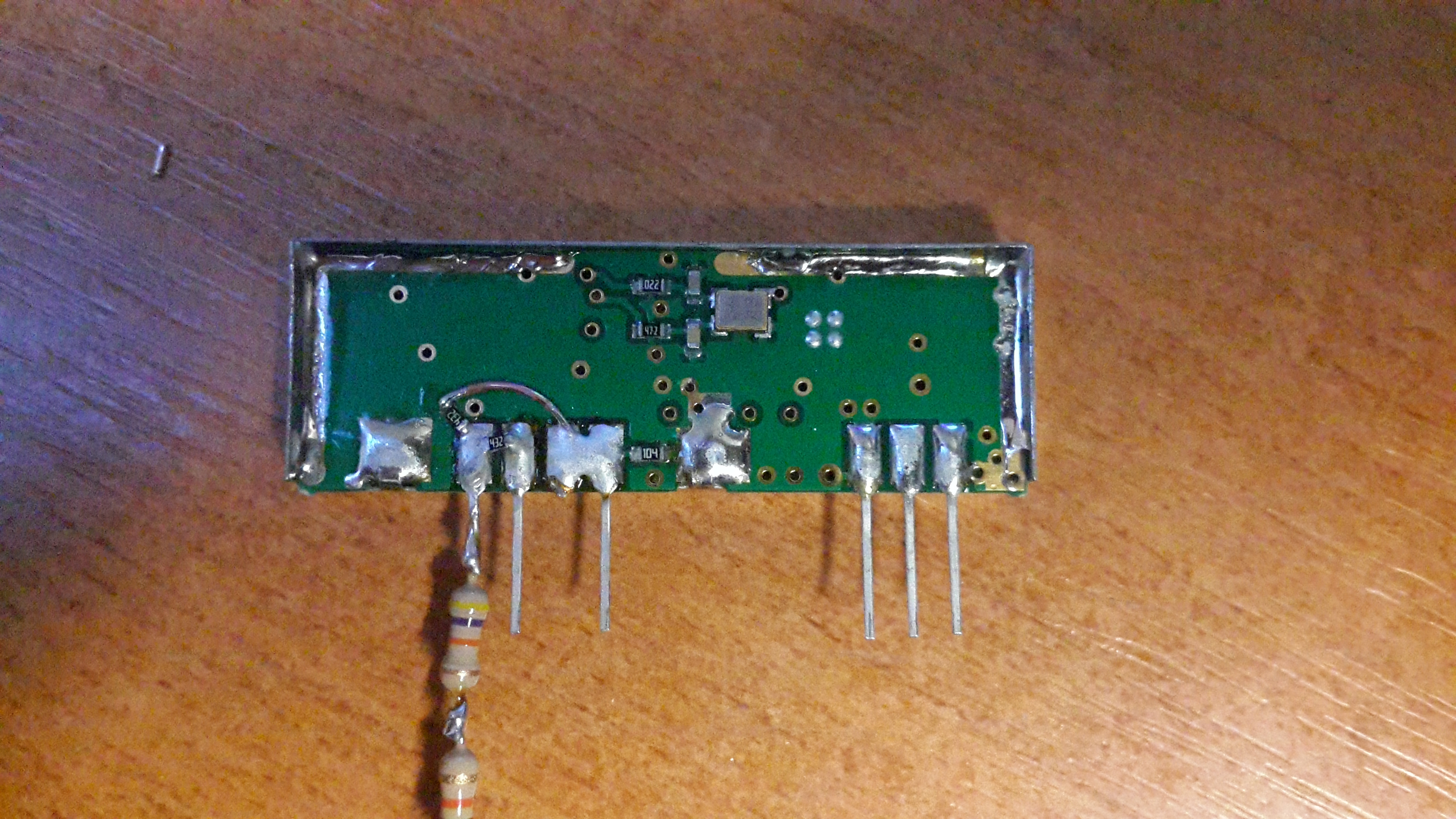
NTX2B with resistors.
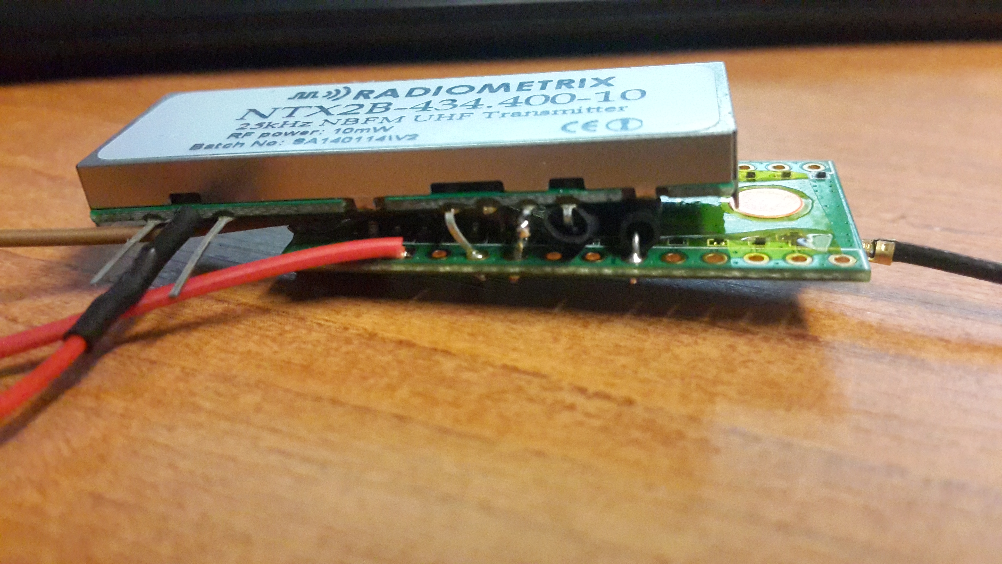
NTX2B / NavSpark sandwich.
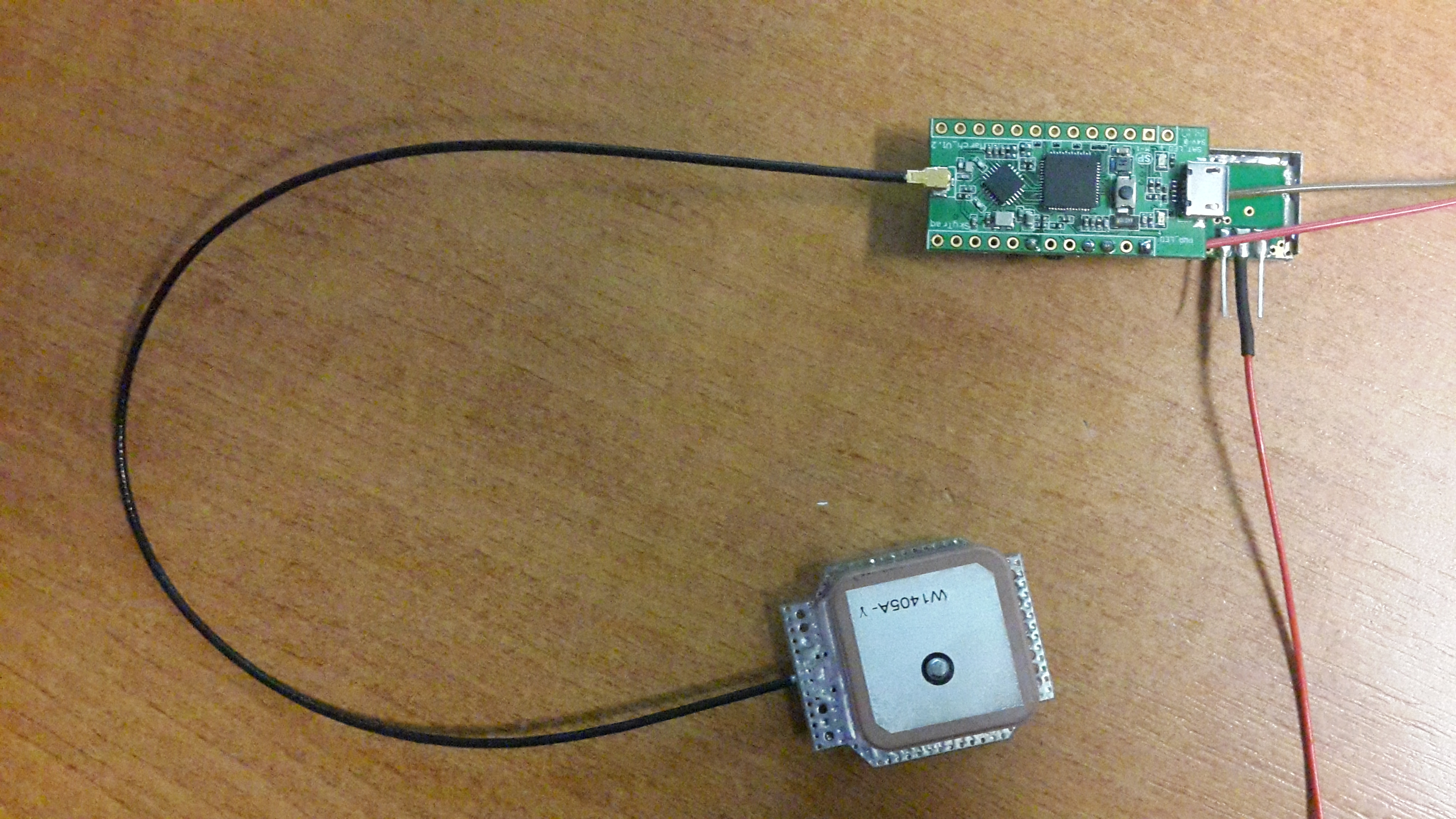
NavSpark side up, showing antenna.
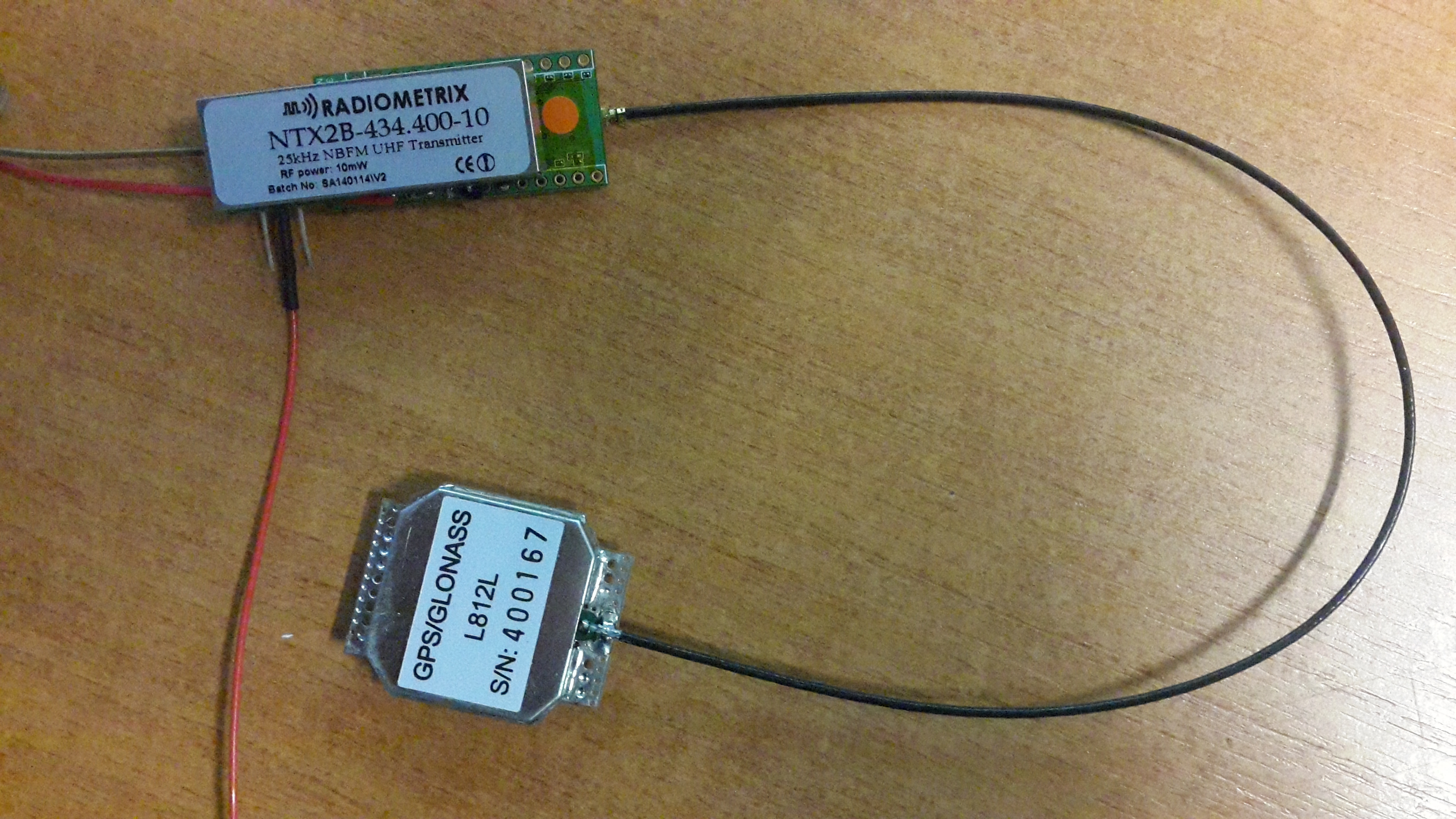
NTX2B side up, showing antenna.
Sitting on my desk, still managed a time fix.
Overall I found the NavSpark hardware very easy to work with, and the coding perhaps even easier than a normal Arduino/uBlox.NTX2 tracker, mainly due to the lack of requirement for a NMEA parser. The NavSpark documentation is a little sparse and badly translated, however everything you need programming wise can be found here. The performance of the GPS in terms of time to first fix is very good, getting a time fix after the first sentence, and a position fix after 4/5 sentences. Once it had aquired a fix and with the NTX2B running, with the supply voltage set at 5.6V and fed to the battery input, the tracker was using about 65mA current.
Would I recommend the NavSpark over an AVR/uBlox based tracker?
I’d certainly consider it! There is probably far more information out there in the AVR world, but if you are just making a simple RTTY tracker then it is certainly a viable option. Just wait for the flight test in the next month or so before rushing out to launch one!
Speaking of flight, what about the COCOM GPS limit?
According to SkyTraq the GPS will only shutdown if 18km altitude AND 1000km/h velocity are exceed simultaneously, meaning it should well be suitable for HAB use.
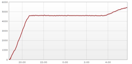
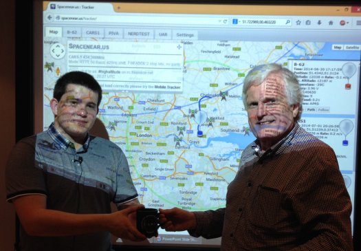
Chris Stubbs M6EDF launched a High Altitude Balloon from the CARS club night at the Oaklands Museum on the 1st of July 2014. This page contains information on the flight of CARS1 for those interested in tracking the flight.
The flight started at 19:50BST on Tuesday.
To see where “CARS1″ is, go to http://spacenear.us/tracker/?filter=CARS1
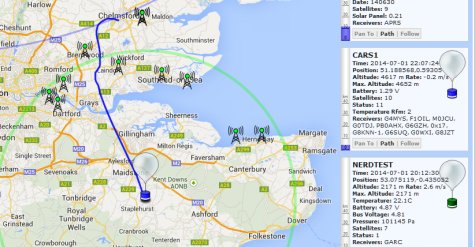
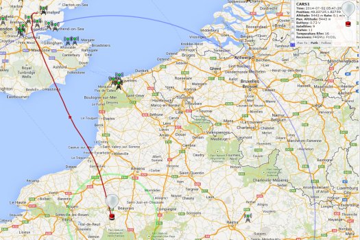
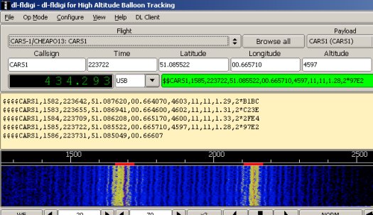
As of 23:05 local, I’m tracking a very strong signal on 434.293MHz USB – Stations tracking at this time include G6GZH, G0TDJ, M0JCU, PB0AHX, G6SUQ, M6EDF, F5APQ, M0PSX, F1OIL, G4MYS, G7OGX, G8KNN-1, G8KNN, G8JZT, G0WXI, ASTRA_J, G0CXW_2, G8APZ
The last packet received here in Southend-on-Sea was at 0354BST, but it continued to be tracked by others beyond that point.
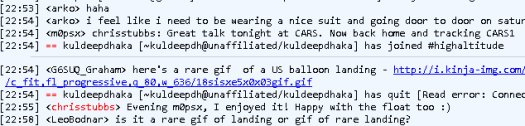
As of 23:00, Chris M6EDF is in the High Altitude chatroom: webchat.freenode.net/?channels=highaltitude – Just made contact to thank Chris for his talk and to confirm he’s very audible in Southend-on-Sea
A short video showing the launch and the tracking of this HAB flight:
Pictures of the launch and presentation 01 July 2014 at Oaklands Museum, for the Chelmsford Amateur Radio Society July Club Night…


For more on this, see CARS-1 High Altitude Balloon Video
Article by Pete M0PSX – http://www.essexham.co.uk/news/cars1-hab.html
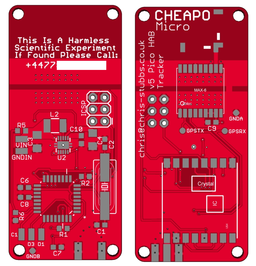
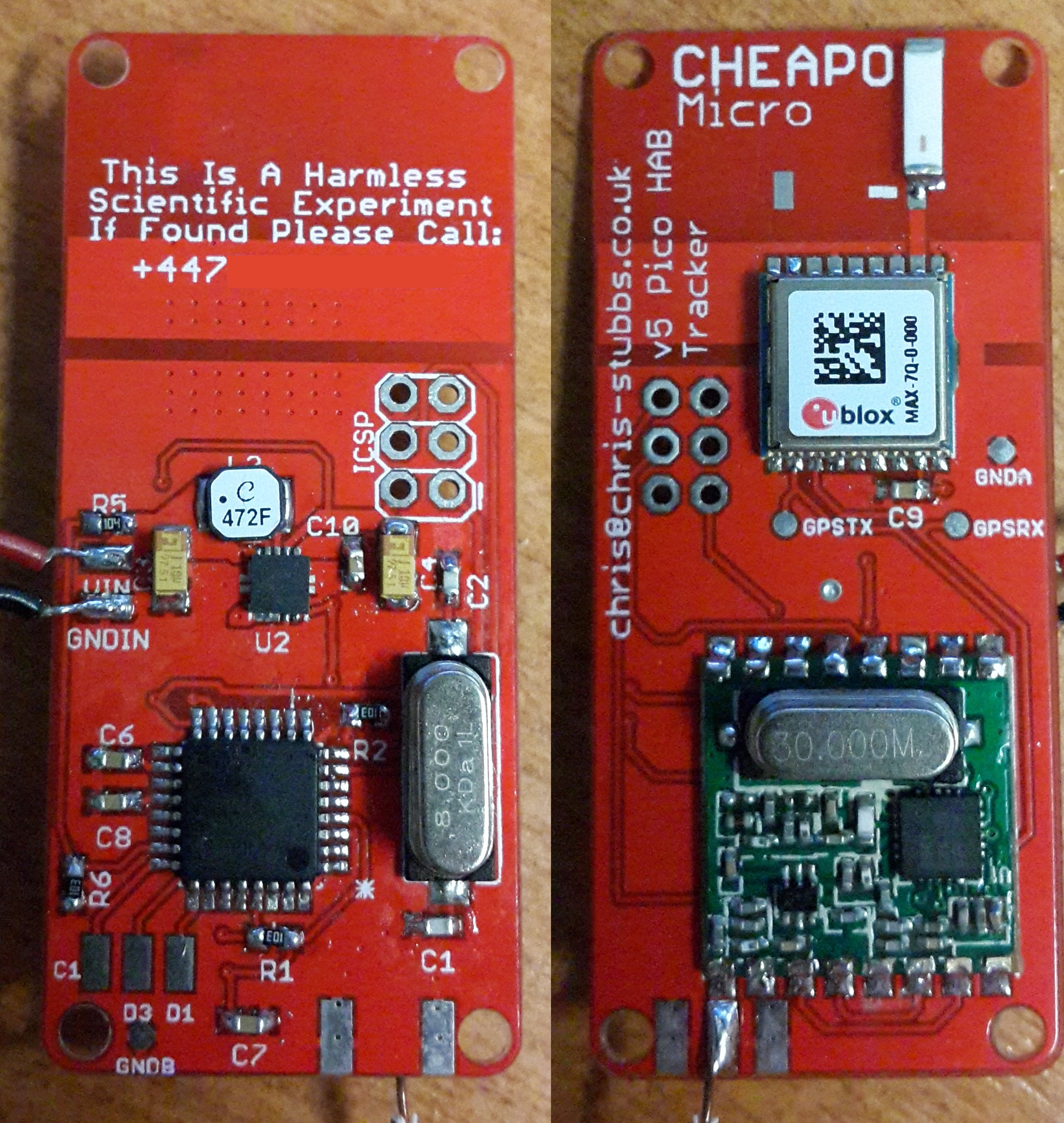
I received the boards for my latest cheapo design revision the other week. The design is very simalar to the previous version, but I am now using the uBlox MAX-7 because of its lower power consumption. I have also shrunk the boards down a little.
The funny arrangement at the top for the GPS antenna is an experiment to see how well chip antennas perform horizontally. So far I have only tested the board in its standard configuration and it all checks out okay! Test flight to follow soon.
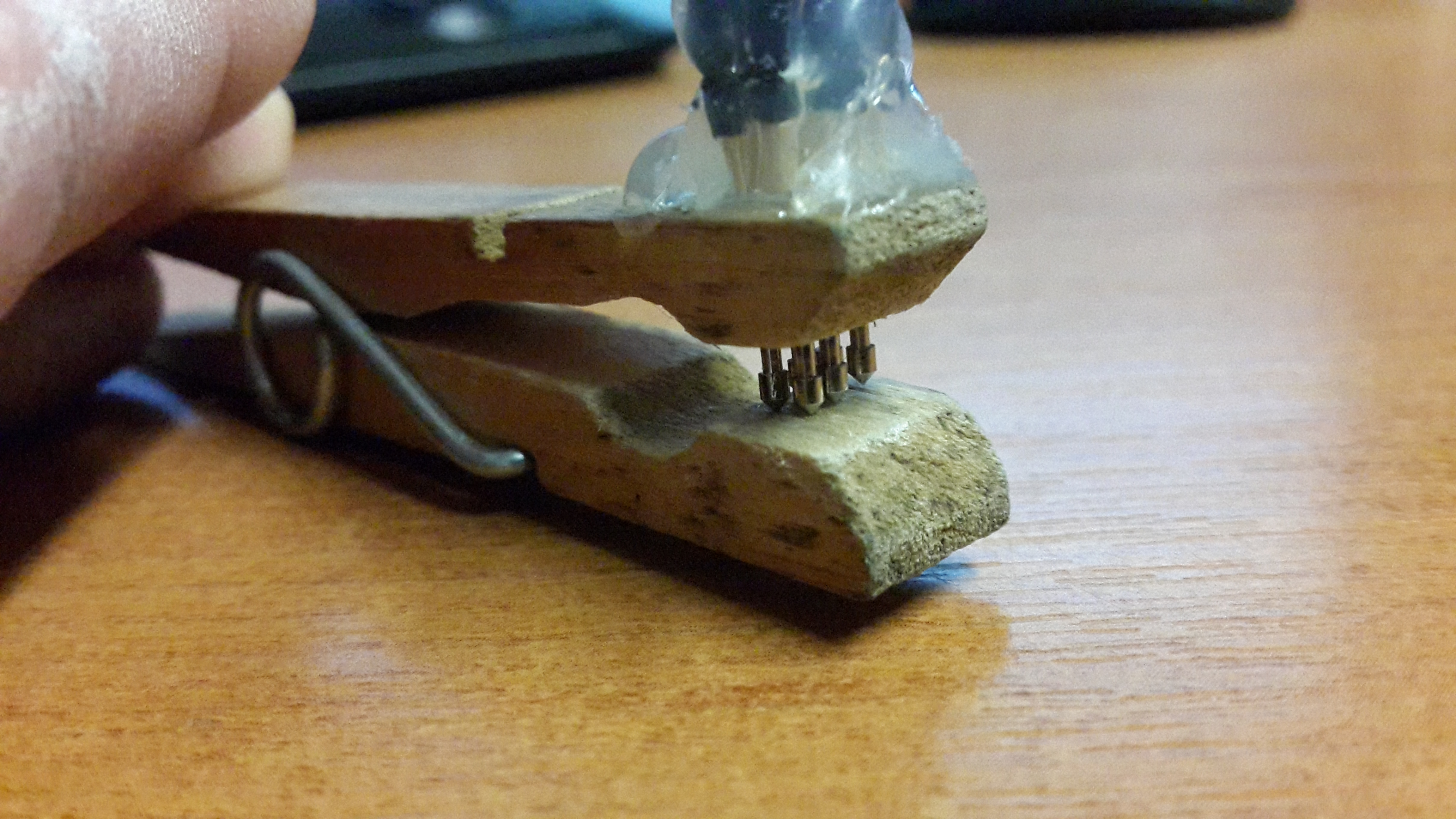
On a side note I also put together a very crude ICSP jig using pogo pins and a clothes peg to avoid having to solder a header onto each board. The alignment isn’t great but does the job.