VOLT-CRANE-O – Hacky Racer Build Log

[This page is auto populated from the Hacky Racers Wiki]


Volt-Crane-O
Voltcraneo racing.JPG
Built By Chris Stubbs
Theme Liebherr Mobile Crane
First Race EMF 2024
Current Status Active
Motor 6x Hoverboard 6.5″ Hub Motors
ESC 3x Hoverboard PCB
Battery 48V 12S3P Li-Ion/LiPo (2x 6S)
Gearbox Direct hub motor
Contact @emfroamer
View all Racer Profiles


Background

Ltm1060.png

Volt-Crane-O is a scratch built, 6 wheel drive, 4 wheel steer, fully functional miniature crane.

The theme is based around a Liebherr 6 wheel mobile crane.

Construction

The chassis is constructed from wood, mostly 2x4. Fixings are mostly wood screws, except the use of M6/M8 bolts where additional strength or rules compliance is needed (bumpers).

The body is also constructed from a lightweight wooden frame, panelled with thin plywood.

Steering uses two M8 threaded tie rods to connect the pitman arm to the trailing spindle arms. The steering column is 25mm bed frame offcut with socket set articulating joint. There is a second pitman arm on the steering column at 90 degrees to produce a back and forth steering linkage to the rear axle, which is then translated 90 degrees again using a pivot to drive the rear tie rods. The steering angle of the rear axle is approximately 1/3rd of the front steering angle, because the rear/mid wheelbase is approximately 1/3 the front/mid wheelbase. No real thoughts were given to steering geometry and the handling is somehow "fine".

The steering components are mostly constructed from offcuts of bedframe, steel angle welded to make U section, or 4x30mm flat steel bar.

Wooden chassis with steering rear view
Wooden chassis with steering front view
Steering components

Powertrain

Volt-Crane-O utilises 6x 6.5″ 350W hoverboard motors, fitted with 4.10/3.50-5 tyres. Regenerative braking is extremely effective if configured correctly, however one motor has been fitted with a mechanical brake from a Xiaomi M365 scooter to comply with the rules.

Power is delivered to the motors using 3x original hoverboard PCBs running a fork of EFeru’s FOC firmware (links at the bottom). A higher current limit is applied to the rear motors to aid traction given the awful weight distribution. Throttle is applied in torque mode, controlled from aliexpress hall effect pedals via an Arduino.

Traction power is supplied by either 2x custom 6S3P Samsung 30T 21700 Li-Ion battery packs, producing 48V total. Each pack contains a 60A DALY BMS, or 2X 6S 9500mAH CHNL Lipos. Another 6S4P Li-Ion set using reclaimed hoverboard 18650’s also exists for testing and running around, but does not perform well enough for racing.


Other Features

The crane boom can be raised and lowered, extended and retracted (2 sections), and the winch/hook raised and lowered by a control panel below the steering wheel.

The boom itself is constructed from 3 telescopic sections of 18mm plywood, running on internal/external 608 skateboard bearings or homemade tubular bearings at each end.

The winch is a 12V caravan/boat trailer winch rated for 900kg.

All other actuation is driven by drill motors with their attached two speed (low gear) gearbox and chuck, which drives an M12 nut along a threaded rod. Opposing bearings are used to take the axial forces rather than relying on the drill. The boom raise/lower rod drives a nut attached to the elbow of an old monitor mount, which in turn raises the boom.

Power is provided by a dedicated 3S lipo.

The boom is lowered in to a cradle and secured directly to the chassis using the steel cable during racing. It fits within the envolope of the body/bumpers.

10 strobing orange hazard lights, 6 orange chasing LED beacons, 2 white headlights and 2 red brake lights illuminate the track for night racing.

An Arduino logs all hoverboard and control telemetry locally via SD card.

Boom extended
Boom extension motor
Boom lift motor

Awards

  • EMF 2024
    • 3rd place overall.
    • 1st place Moxie.

BOM

coming soon

Limitations

Steering wheel snapped off.

Sluggish on mud/grass.

Heavy (100kg).

Happily pops 30A fuse if accelerating too hard/long.

Resources

Twitter Account @EmfFRoamer

The Hoverboard firmware, Arduino code, and CAD on GitHub

Remote control Pi code on GitHub

Chris’ website


For the latest news, posts and discussions about everything Hacky Racers, head over to the Facebook group.

CYBR TRK – Hacky Racer Build Log

[This page is auto populated from the Hacky Racers Wiki]


CYBR TRK
Cybr trk profile.jpg
Built By Chris Stubbs and Dom Tag
Theme Tesla Cybertruck
First Race EMF 2022
Current Status Active
Motor 4x Hoverboard 6.5″ Hub Motors
ESC 2x Hoverboard PCB
Battery 48V 12S3P Li-Ion (2x 6S)
Gearbox Direct hub motor
Contact @emfroamer
View all Racer Profiles


Background

Cybr trk rgb.jpeg

CYBR TRK started life in 2022 as the EMF Roamer; a publicly controlled, raspberry pi powered robot, that could roam the EMF site. This was a follow on project from the much smaller EMF Roamer in 2018. One of the main objectives was to also be as Hacky Racers legal as practical.

The theme is a loose caricature of the Tesla Cybertruck, rather than an original donor vehicle.

Interview

Construction

The chassis is constructed from wood, mostly decking frame offcuts, utilising recycled hoverboard components wherever possible. The front wheels are able to articulate using a hoverboard casting as a joint, in a crude suspension to keep 4 wheels on the ground.

The body is also constructed from a lightweight wooden frame, panelled with thin plywood. This is removable from the chassis to enable maintenance and transport.

Steering uses two M8 threaded tie rods to connect the pitman arm to the leading spindle arm. The steering column is 25mm electrical conduit with socket set couplings. No real thoughts were given to steering geometry (bad) as this was a retrofit from the fly-by-wire servo system.

Wooden chassis
Wooden body
Steering components

Powertrain

CYBR TRK utilises 4x 6.5″ 350W hoverboard motors, fitted with 4.10/3.50-5 tyres. Regenerative braking is extremely effective if configured correctly, however one motor has been fitted with a mechanical brake from a Xiaomi M365 scooter to comply with the rules.

Power is delivered to the motors using 2x original hoverboard PCBs running a fork of EFeru’s FOC firmware (links at the bottom). A higher current limit is applied to the rear motors to aid traction given the awful weight distribution. Throttle is applied in torque mode, controlled from a playstation racing pedals set via an Arduino.

Traction power is supplied by 2x custom 6S3P Samsung 30T 21700 Li-Ion battery packs, producing 48V total. Each pack contains a 40A continuous rated BMS. A second 6S4P set using reclaimed hoverboard 18650’s also exists for testing and running around, but does not perform well enough for racing. Block diagram of electrical configuration as configured for EMF Camp (local & remote mode)

Electrical block diagram

Other Features

Cybr trk trailer.jpg

A fold up trolley makes an effective trailer for running gear from the car park to the track!

Originally the car contained over 300 individually addressable RGB LEDs. It could produce an impressive RGB underglow, front headlight bar, and rear brake bar with animated indicators. This number has however declined as they were damaged in races and modifications.

When deployed as the EMF Roamer, the vehicle could be controlled by anyone using a web browser. This used a websockets connection for control, and jsmpeg for live video. A presentation was given at EMF with more information, but recordings could not be published. Presentation without audio available here.

Cybertruckservo.jpg

A windscreen wiper motor was originally used as a steering actuator with a pot for feedback, all hooked up to an arduino PID controller. The setpoint could then either be fed from the steering wheel (an old playstation controller), or the Pi for remote control. Using the arduino also allowed current limiting and fault detection, to prevent fire if it gets jammed. Turns out as a neat trick, you can run a PID loop to control the servo angle, and a PID loop to control the max current, and just take the minimum output from either controller as the PWM drive! This was eventually removed in place of basic mechanical steering, at the request of Hacky Racers on safety and legality basis.

The Pi logs all hoverboard and arduino telemetry locally via MQTT/NodeRed/Grafana.

Awards

  • Fully Charged Live 2023
    • 1st place overall.
    • 2nd place race position.
    • 2nd place on Moxie points.
  • EMF Camp 2022
    • Beat slowest ever hacky racers lap (previously held by EMF Roamer in 2018)

BOM

Item Cost Total
Tyres £103.25 £371.15
Wood for frame/body £40.00
Control PCB £32.00
Swegway 1 £30.00
Swegway 2 £30.00
Chassis alu £20.00
Motor drive enclosures £18.96
Light bar £12.45
Paint £10.00
Bumper steel £10.00
Wire £10.00
Rod ends £9.31
Chair £8.00
Pedals £7.86
LED strip £5.60
Steering Wheel £5.00
12V reg £4.89
Steering brackets £4.46
Steering bolts £3.32
Steering column £3.25
Steering rod £2.80
Battery box Excluded
Brake kit Excluded
Brake standoffs Excluded
Kill switch Excluded
Bumpers Excluded
Batteries Excluded
Fuse Excluded

Limitations

Tips over a lot.

BMS’s run extremely hot.

Happily pops 30A fuse if accelerating too hard/long.

Resources

Twitter Account @EmfFRoamer

The Hoverboard firmware, Arduino code, and CAD on GitHub

Remote control Pi code on GitHub

Chris’ website


For the latest news, posts and discussions about everything Hacky Racers, head over to the Facebook group.

Building a Queue for the EMF Roamer with the Vonage SMS API and PHP

If you haven’t heard of Electromagnetic Field (EMF) Camp, imagine a field in the quaint English countryside, temporarily populated by 2,500 curious tech/maker enthusiasts; fiber internet, radio masts, robotic bartenders, lasers illuminating the sky, and wild/wacky inventions as far as the eye can see.

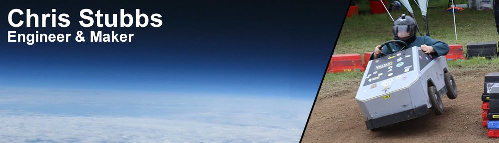
One of these wacky inventions was the EMF Roamer, a quarter-scale wooden Tesla Cybertruck, deployed to roam around the side, controlled by anyone over the internet!

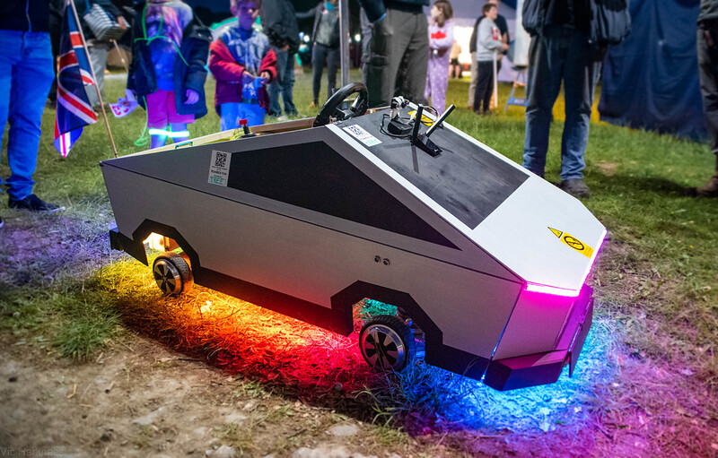
Just allowing people to drive it line of sight wasn’t good enough! Especially not in the world of the Internet of Things. Live video from a camera, along with the location on a map is streamed to the user while they have control of the roamer.

A free for all in terms of control would have been a mess, so we devised a queue system. People could join the queue in their web browser and wait their turn, or provide a mobile phone number to receive an SMS when their turn is up (thanks Vonage!). The queue system is “serverless”, in that it does not require a dedicated server. Instead, it runs on simple shared hosting, with PHP coordinating the queue on-demand, which is stored in a MySQL database.

To build a queue system for yourself, take a look at the WebUserQueue project on my GitHub, or follow the guide on the Vonage Developer Blog.

True 3 wire SPI on the ESP32 (detaching MISO from the pin matrix)

I screwed up.

On my latest board using an ESP32 I connected an LED to pin 19, but it would never light up.

I wasn’t using the pin for anything else, and sources online didn’t seem to indicate any problem with using it as a GPIO output. I was however using the VSPI port to connect to an ePaper display, but it was only physically connected in 3 wire mode.

When the display was initialised, I could no longer control the LED.

Fortunately I had read about a handy feature of the ESP32 known as the GPIO matrix. It allows the physical pins of the chip to be mapped (and importantly unmapped) from an internal signal.

Poking around inside esp32-hal-spi.c the signal name of “VSPIQ_OUT_IDX ” can be found.

A little further on an example of detatching a signal can be found here.

pinMatrixInDetach(signal, false, false);

Meaning all we need to run to detatch the MISO of VSPI is:

pinMatrixInDetach(VSPIQ_OUT_IDX, false, false);

And it works!

The EMF Roamer

While packing for EMFcamp 2018, I came across a small tracked robot chassis at the back of my cupboard. It was instantly obvious that this needed to be turned into a small internet controlled robot for the camp. It could be deployed and roam around the site, controlled by anyone!

Just allowing people to drive it line of sight wasn’t good enough! Especially not in the world of raspberry pi’s. The video from a raspi camera should be streamed to the user while they have control. A GPS module showing a roamer icon on the official EMF map was also a must-have at this point.

A free for all in terms of control would also be a mess, so we devised a queue system. People could join the queue in their web browser and wait their turn, or provide a mobile phone number to receive an SMS when their turn is up (thanks nexmo!). We also planned twitter integration, but didn’t get our account approved for developer use until after the event. Cheers twitter. The queue system was hosted by Hostgator ,but it ground to a painfully slow halt where pages took almost 60 seconds to use, forcing us to move the whole thing over to Servage. I think I will be ditching Hostgator soon after this experience.

The first step was to get a low latency video stream working. Youtube does offer a low latency mode, but I found that it still had a latency of 5-10 seconds. Nowhere near good enough for live control! Youtube streaming was however still a nice idea, as it would allow people to watch the stream as they wait in the queue. Step in MJPEG-Streamer. It can produce a stream with extremely low latency. Perfectly good enough for control. The only difficulty being that once the MJPEG streamer was using the raspi camera, it was then locked and could not be used by other programs.

Step in horrendous FFMPEG commands! After far too much poking around online, with lots of commands that didn’t work, or did something slightly different that broke when I tried to modify them, I found a winning combination. FFMPEG picks up the MJPEG stream, adds a fake audio source (required for youtube), and sends it out to the youtube ingest server over RTMP. This FFMPEG command sat inside a shell script that would monitor the log, and restart the process if no new frames were sent in a few seconds.

My initial plan for controlling the motors was to run an HTTP server on the pi, and control the GPIO pins depending on which directories were accessed. This was accomplished through a python/flask script. The motors themselves are controlled by a [chip] H bridge driver chip.

The GPS side of things was pretty trivial using this python port of TinyGPS. The data is sent to a webserver via GET where it is then stored in the MySQL database. The official EMF map was open source, but after a couple of days of trying, we were’t able to integrate a roamer icon on to the map nicely. Instead as a last minute bodge, I centred an icon on top of the map in straight up HTML, and repositioned the map to reflect the position.

In order to get the best possible WiFi coverage and quality, we purchased a high gain antenna/adaptor from Amazon, which was supposedly Pi compatible. This worked on my home WiFi, but actually felt more laggy than the el-cheapo Netgear adaptor we were initially using.

When we arrived at emfcamp, the fancy WiFi adaptor just flat out refused to connect to either their legacy or insecure 2.4GHz networks. I can only put this down to an incompatibility with WPA2 enterprise. This can apparently be fixed by recompiling some drivers, if you have the patience. We did not have the patience, so taped the Netgear adaptor to the high gain antenna on a USB extender. Coverage was a little patchy, and it was unreachable for several seconds when it roamed between AP’s.

This patchy WiFi performance was a massive problem to the controls. Sometimes the stop packet was lost in transit, and the motors would lock on moving in a direction. To try to mitigate this, I had programmed a 3 second dead mans switch, which would stop the motors if no new packers were received. Three seconds of driving in a random direction however was a pretty poor experience. I quickly replaced the HTTP control with websockets, and the results seemed much better. I was able to reduce the dead mans switch to one second, and it seemed to be needed less often.

All of these scrips were started using cron jobs to run @reboot.

Tiny tracks and long grass were a terrible idea. Initially you were able to turn on the spot by driving one motor forwards, and the other back. I ended up disabling this as it caused the tracks to ingest way too much grass, and was probably the main culprit to us shredding the first gearbox. It also fell over at almost any opportunity.

This however did not stop one keen driver from taking it for a lap around the Hacky Racers track, and officially scoring the worst time of the entire event.

Some stats:

  • GPS updates: 1632
  • Distance driven: 3.217918922 miles
  • Number of attempted users: 307
  • Number of users who drove: 253 (including us testing it)
  • Number of unique drivers: 116
  • Hours of video: 6:19:29
  • Number of talks crashed: 2 (stage A, first one here, second one not captured)
  • Number of times the tracks came off: >2
  • Number of times people tweeted it wasn’t working: 6
  • Time it took to load the homepage on our old shared webhost: 30-60 seconds
  • Official hacky racers lap time: 6:42 (slowest of the whole weekend)


Improvements:

  • Bigger chassis, bigger tracks, or just wheels.
  • Diversity WiFi antenna. Use a bridge to LAN?
  • Timestamp video (aligning patch YouTube DVR with GPS was a nightmare).
  • Make the map less broken.
  • Night vision camera.
  • Something to discourage people from standing in front.
  • Battery voltage monitoring.
  • RF gateway from wired server for remote control (LORA?)
  • Moar RGB
  • Some kind of game. Collect/chase things on the map?

I used Excel 3D Maps to produce the map animation from CSV GPS logs.

µTesla – One inch tesla coil

For the Hackaday square inch PCB contest, I decided to have a go at miniaturising the slayer exciter circuit often used on chip musical tesla coil kits often found on ebay and aliexpress.

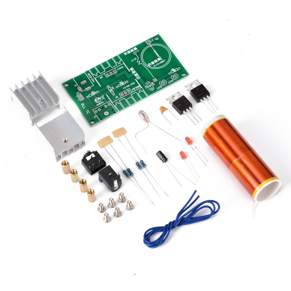
It turned out to be fairly straightforward!

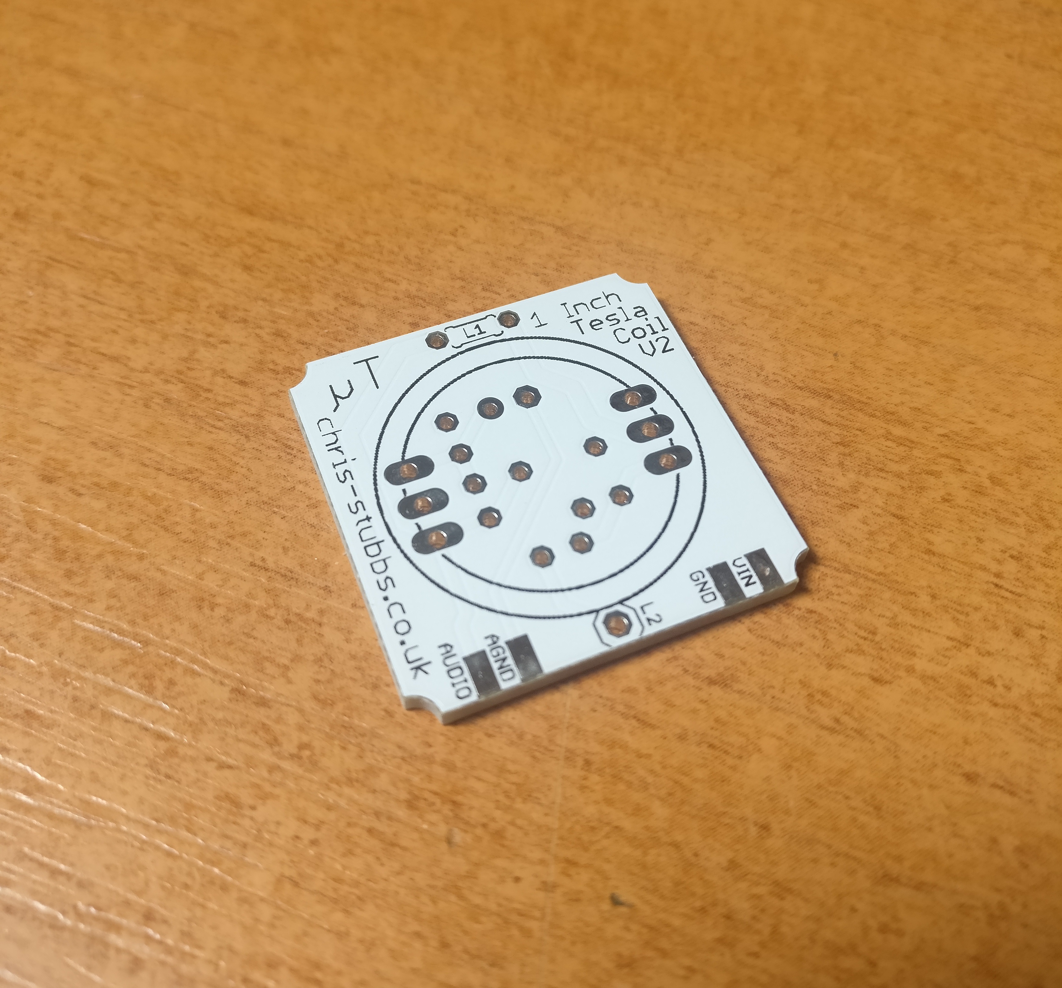
The details of the project can be found at the hackaday.io page.

TP-Link HS100 WiFi socket controller for Windows

I own a couple of TP-Link HS100 WiFi sockets.

When I’m using my PC, it’s a minor pain to have to unlock my phone, open the Kasa app, wait for it to finish displaying the infernal splashscreen, then turn on my socket.

What I wanted was a program sitting in the windows tray to control them. So that’s what I made. It’s in VB.NET. All you need to do is toggle a switch icon on your taskbar.

This is heavily based on the API research over at itnerd.space
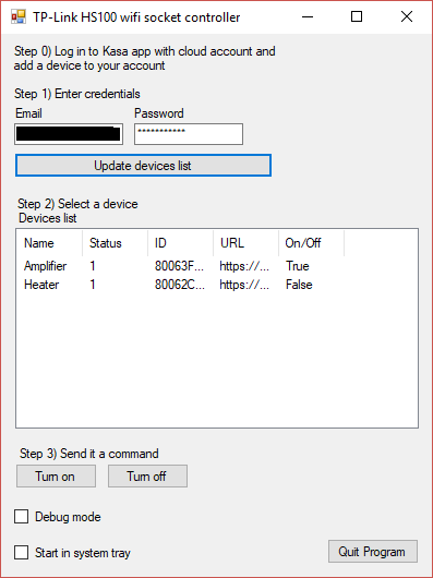
Instructions:

  1. Log in to a cloud account in the Kasa app, and make sure at least one device is associated with your account. Give them names if it’s helpful.
  2. Download and install my program.
  3. Put in your Kasa account details and click the “update devices list button”
    The list should be populated with the details of each device you have connected. You can click each one and control it from this screen. Notifyicons will also be created in the system tray for each device.
  4. If you click the x (close) in the top right of the program, it will minimise to the tray.
    You can mouse over the tray icons to see their name, and click them to toggle the state. Right clicking any icon will open the menu again.
  5. I recommend you tick the “start in system tray” box and add a shortcut to the program in your startup folder.

Changelog:

1.0.0.4 – 15/05/2018 – Fix errors when a device in your account is offline.

2.0.0.0 – 23/06/2019 – New features: CLI mode. Copy ID to clipboard. Bug fixes: Better management of tray icons. Removed from alt-tab list when minimised to tray.

2.1.0.0 – 25/06/2019 – New features: Start with Windows. Create on/off timers for devices. Automatically turn devices on/off on program launch/exit.

Download installer TPLink-HS100-controller-2.1.0.0

Download source code from GitHub.

[GUIDE] Make windows taskbar always show an icon

[GUIDE] Command line interface

This program has no affiliation with itnerd.space or tp-link. I accept no liability for its use. This program is provided without warranty/guarantee.

SXHAM1 – CHEAPO18 flight for EssexHAM/TXFactor/RSGB – 31/05/15

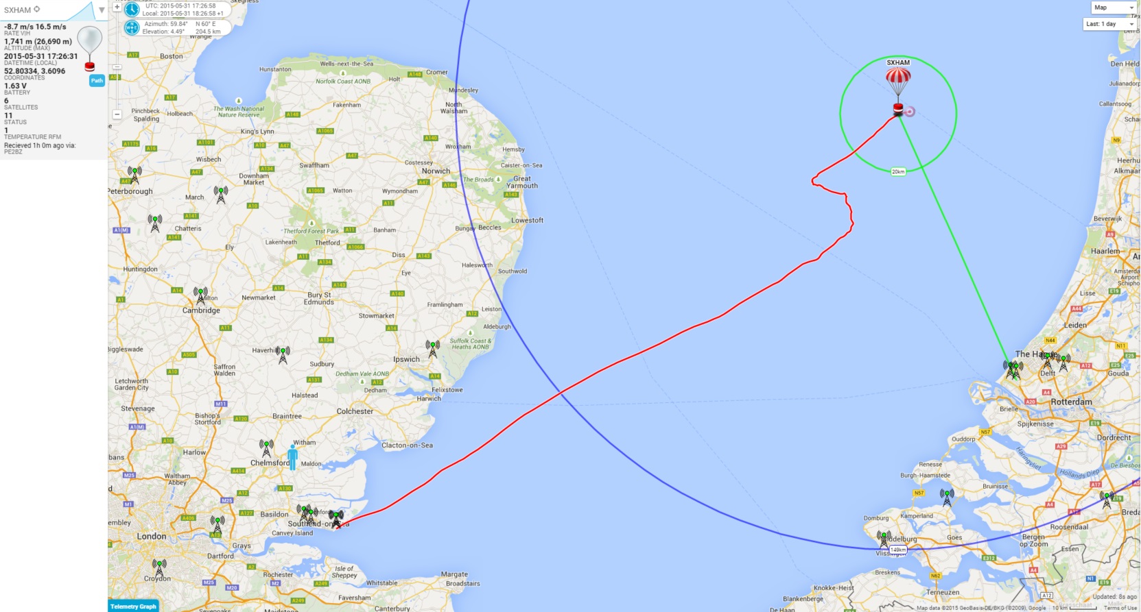
I was approached by Pete M0PSX to do a HAB launch for a promotional video by the RSGB.
The launch took place from the EssexHAM field event at Shoebury East Beach on Sunday the 31st of May.
There were a few other radio amateurs present operating on HF and 2m, as well as a couple of guys flying drones.
Footage was captured by a group called TX Factor, who are doing a piece for the RSGB promoting youth and interesting new activities in amateur radio.

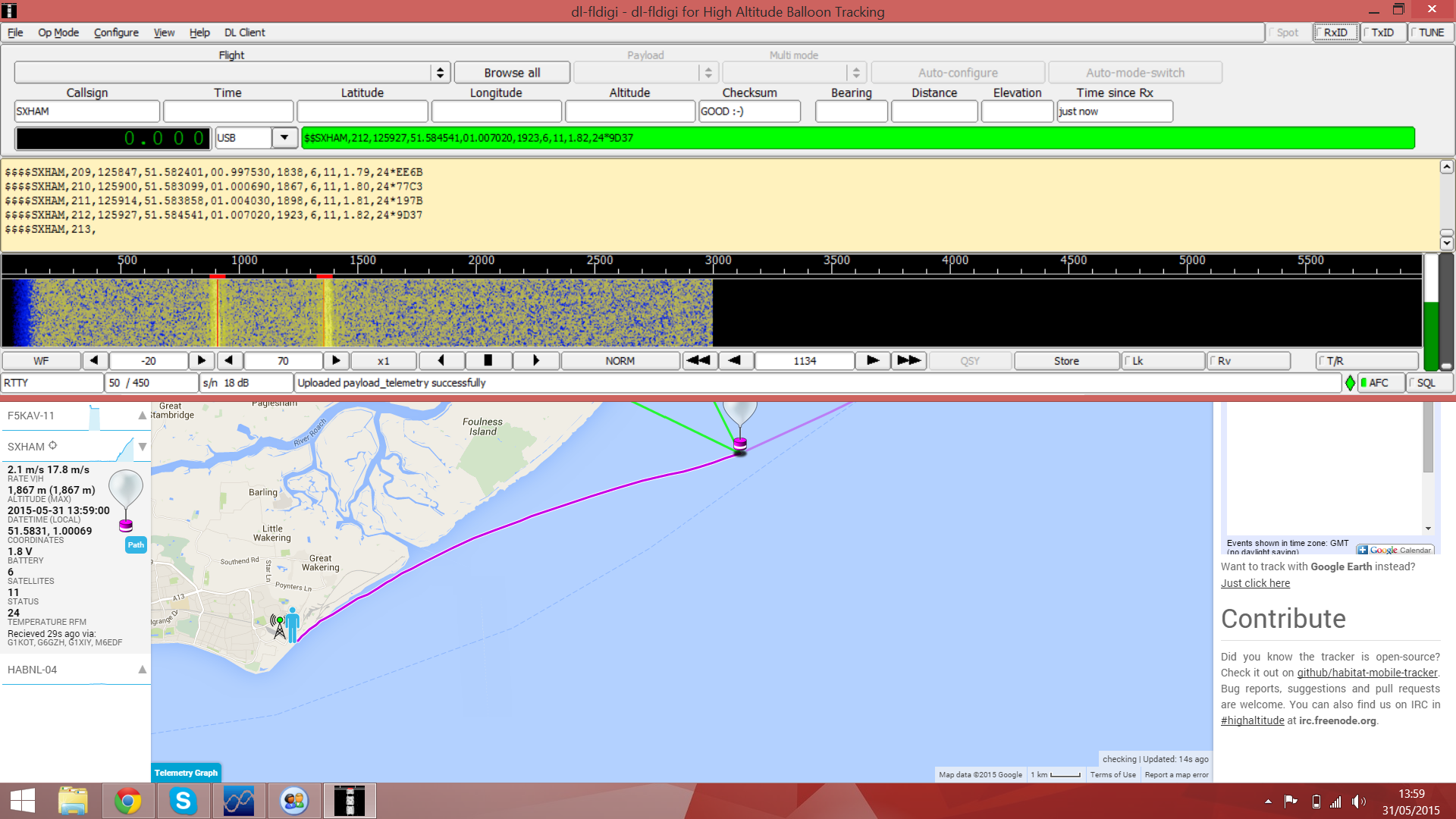
We launched a Cheapo Micro tracker under a 100g Pawan balloon, then tracked the flight from the event using a couple of RTL-SDR’s with a yagi and a 2m/70cms magmount.

Yagi


exham


sxhamlanding


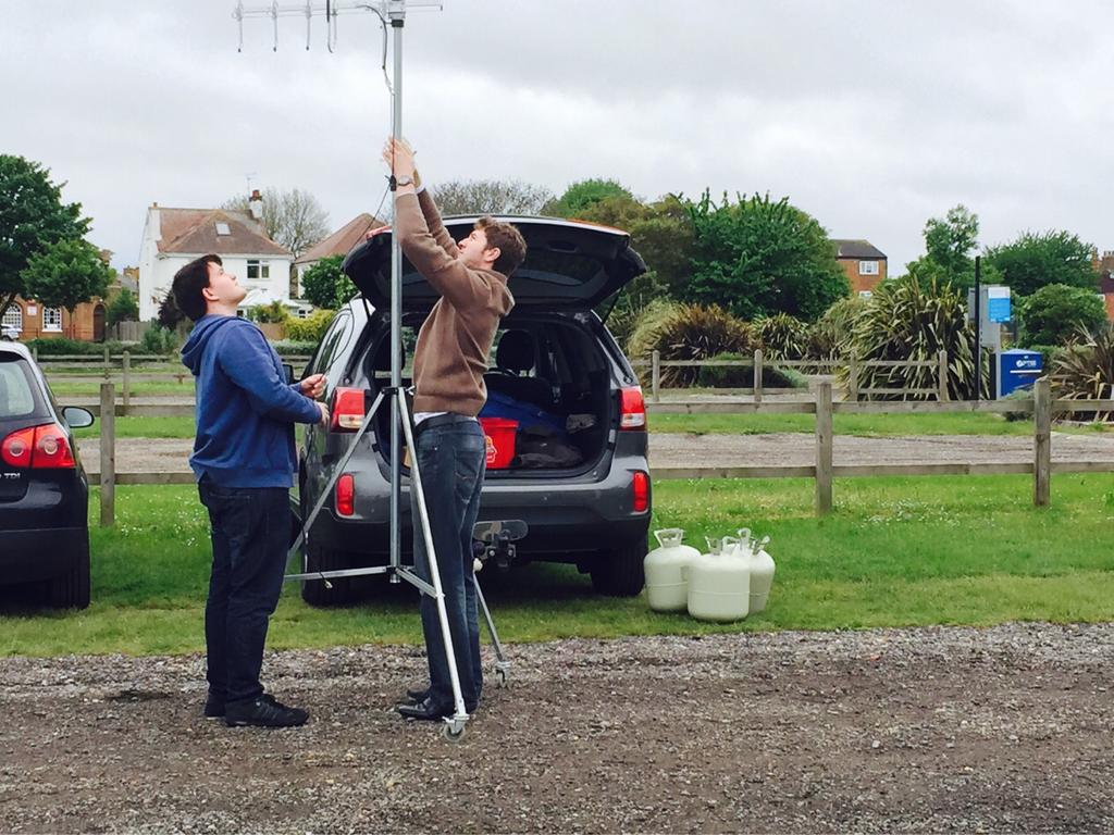
Video and photos credit Pete M0PSX

Footage from TX Factor to follow.