UKHASnet WiFi node using ESP8266

Since the UKHAS conference in August I have been playing with some UKHASnet nodes, which are “A simple wireless network aimed for use with low power licence exempt wireless modules”.
The system was developed by members of the UKHAS community, but is not specifically aimed at ballooning (however can be used for it).
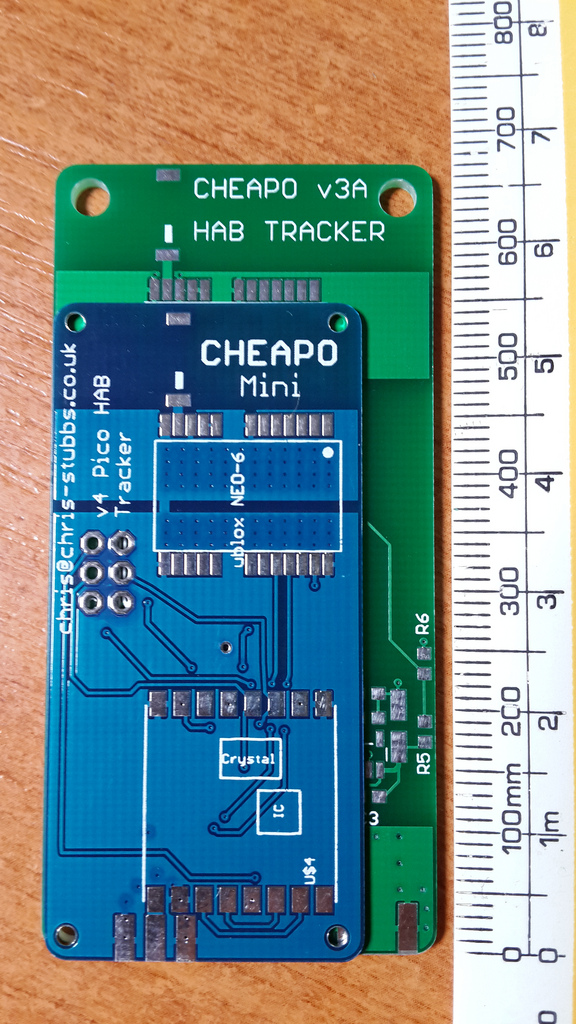
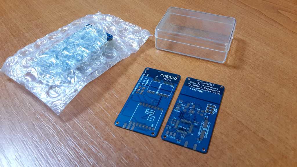
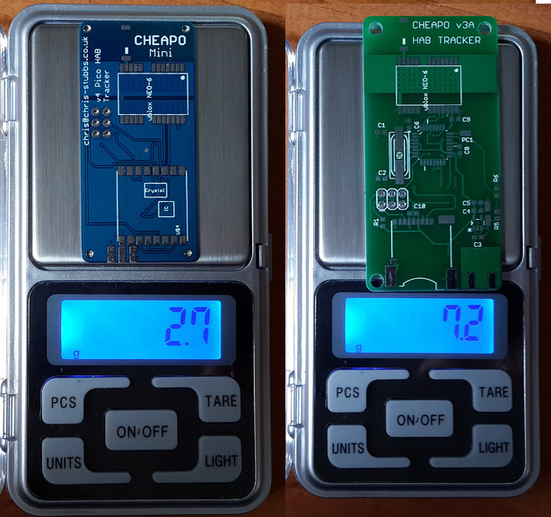
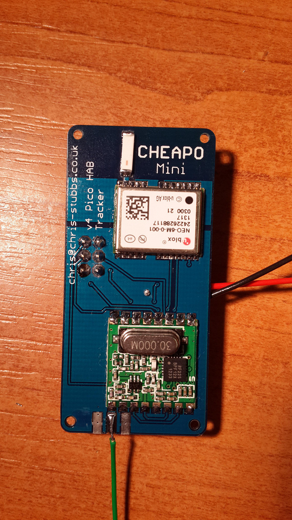
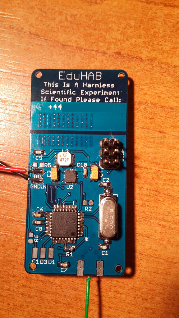
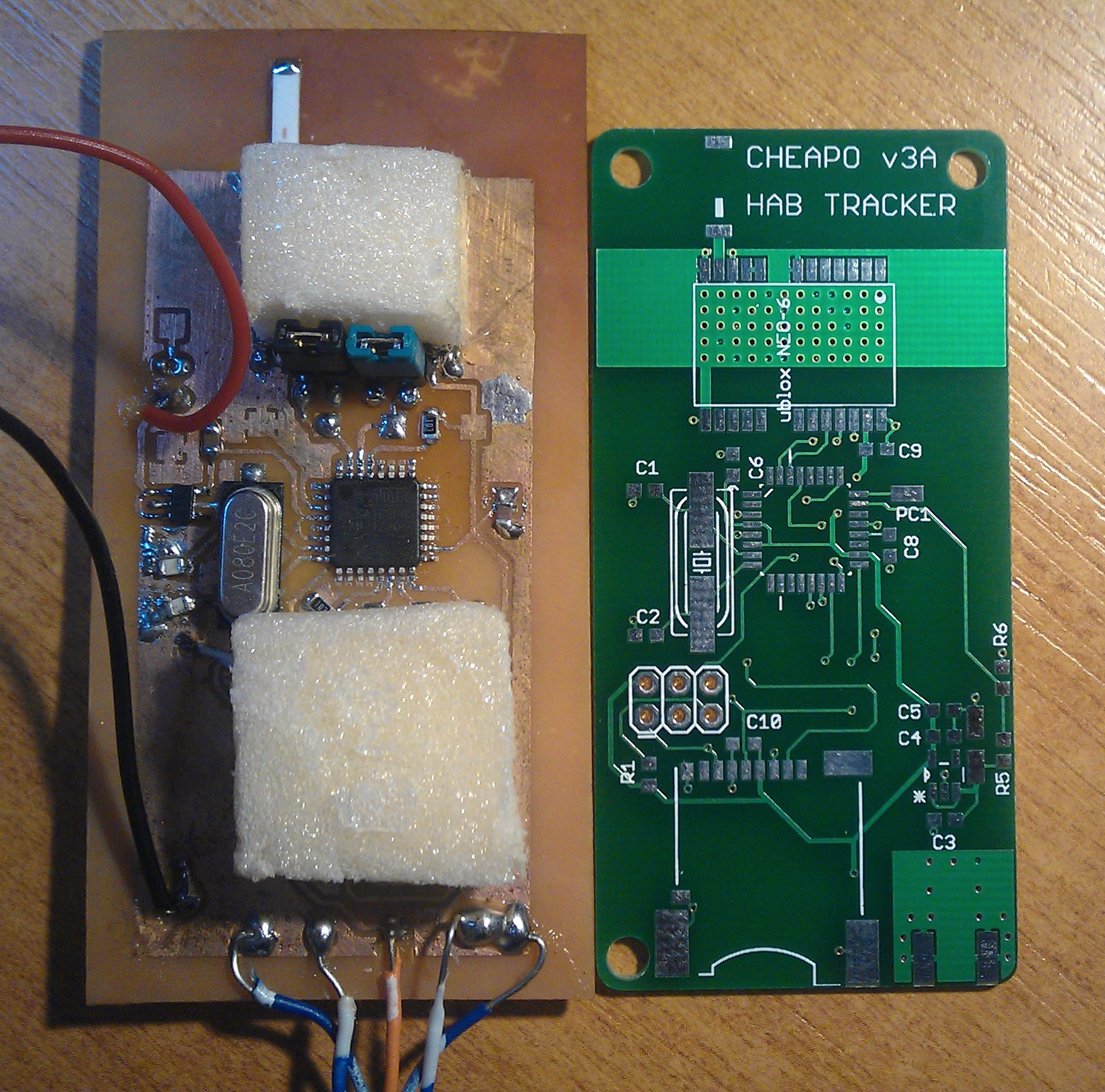
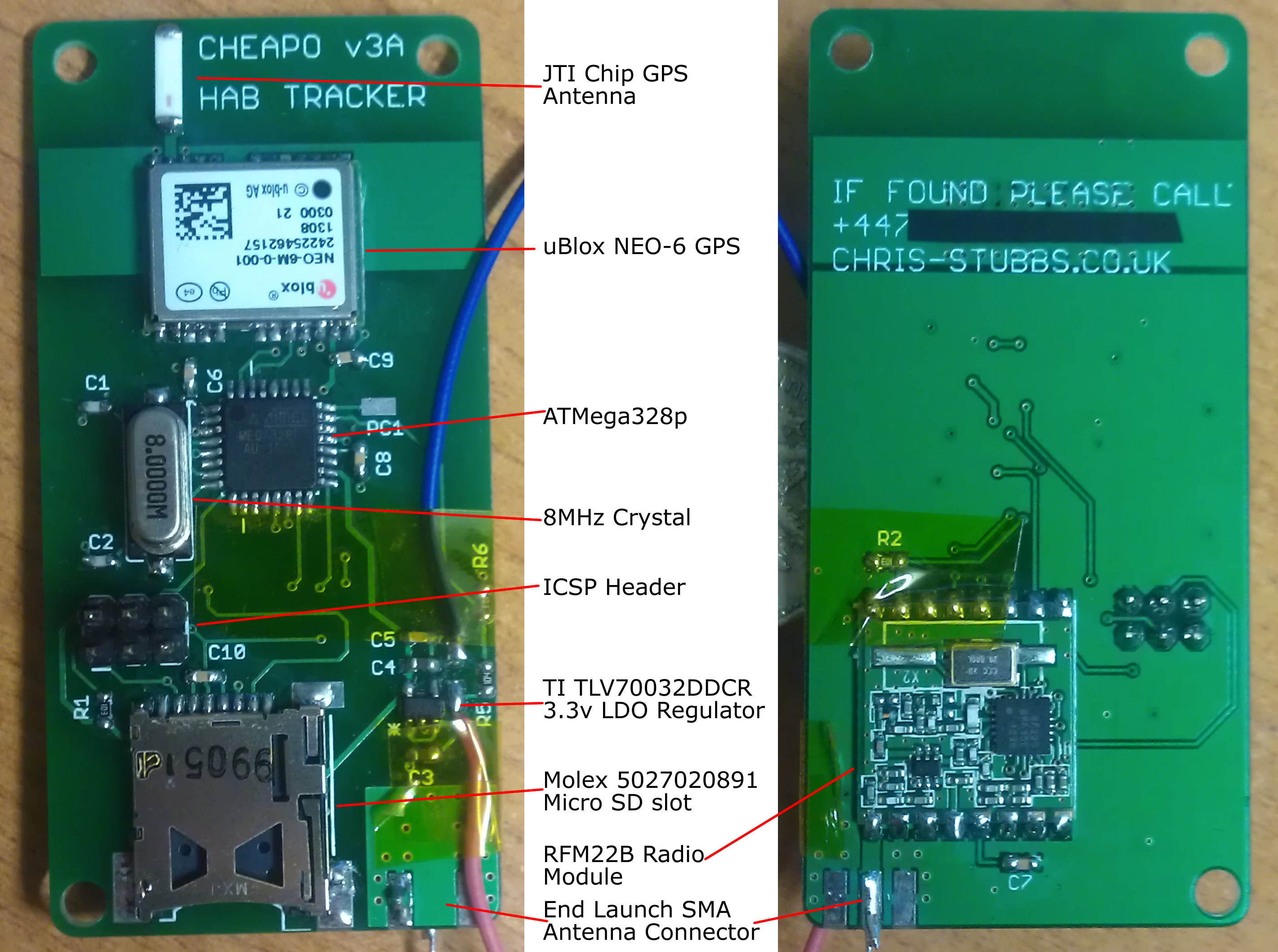
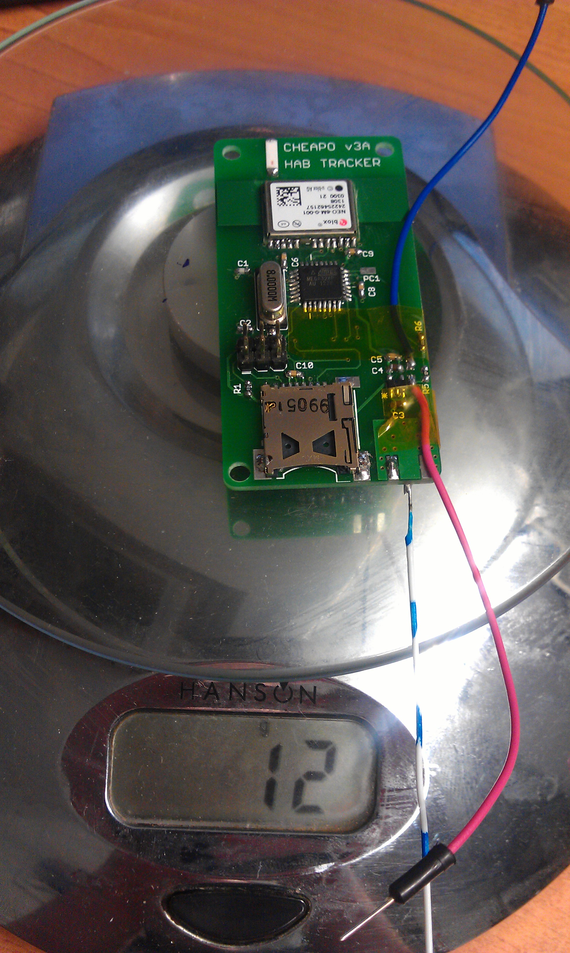
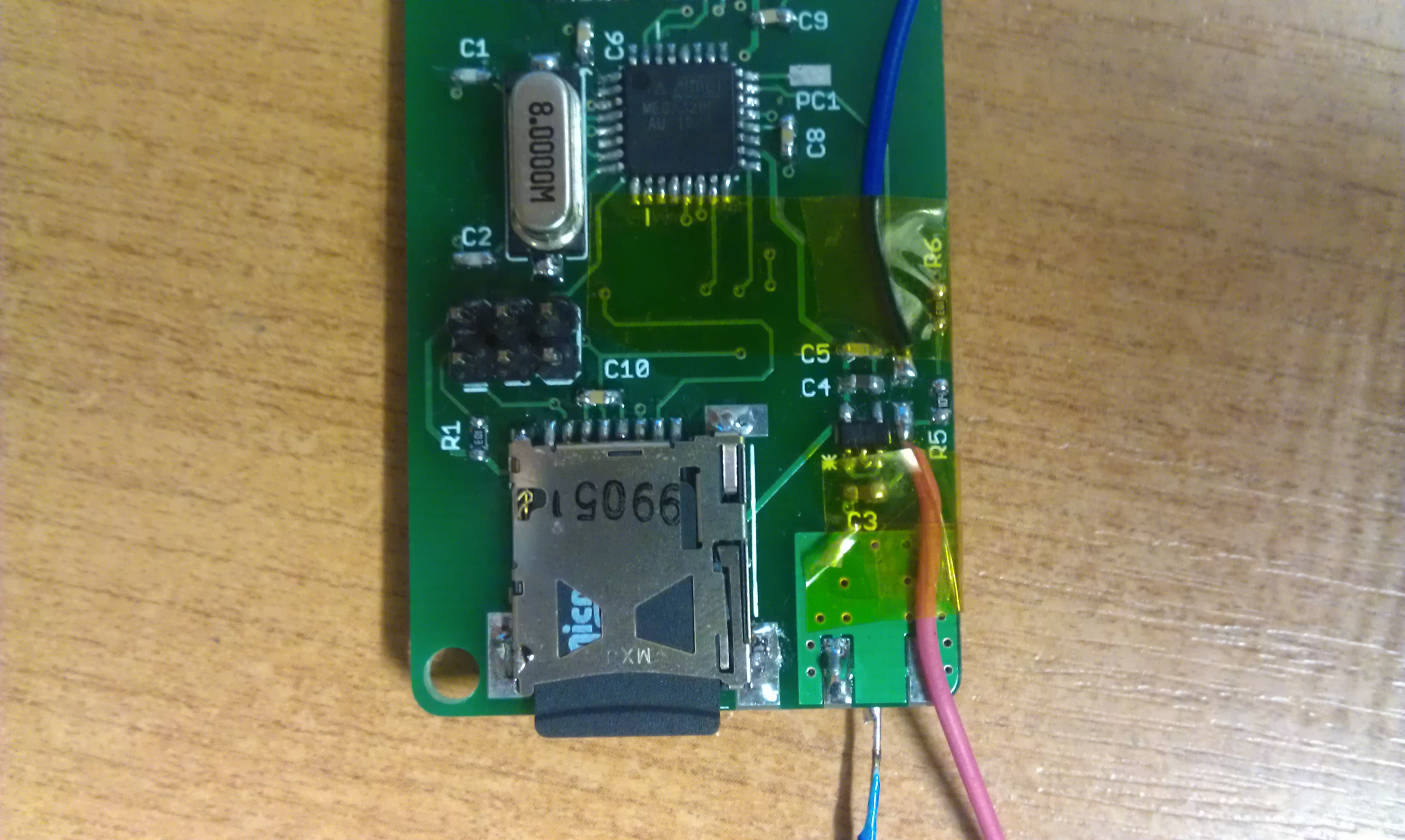
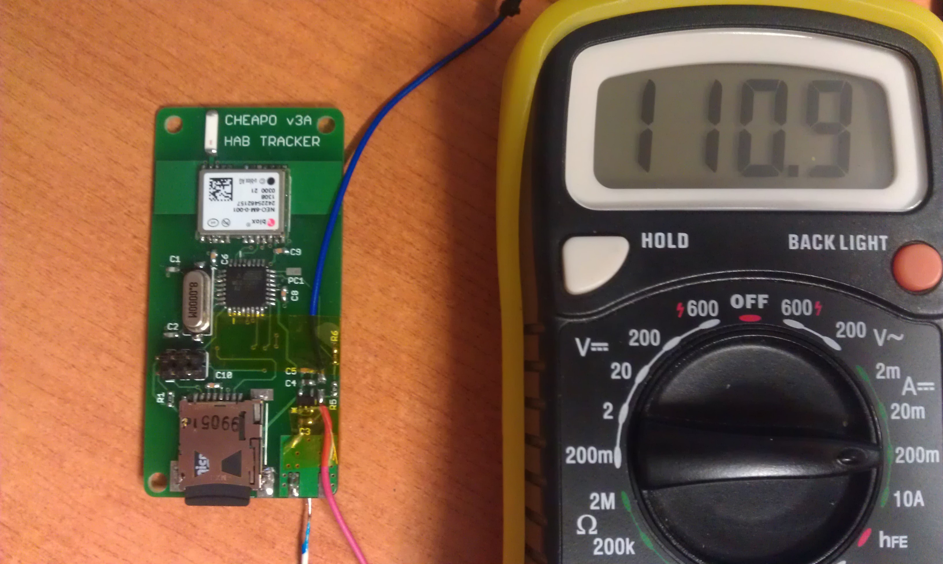
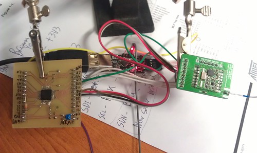
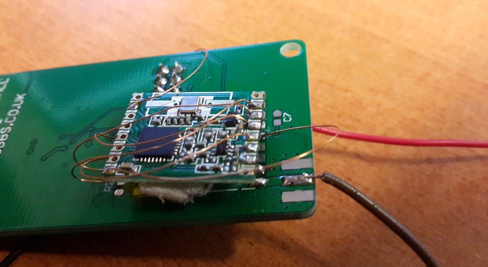
I have 2 LPC810 based nodes designed by James Coxon, and an AVR node from Phil Crump. After I had these set up, I loaded Phil’s code onto an old Cheapo v3 PCB and bug soldered a RFM69 onto the back. This made a pretty effective GPS node and after some tinkering I had positions being uploaded to ukhas.net.

15129165171_617a8f28db_b

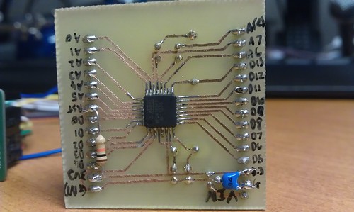
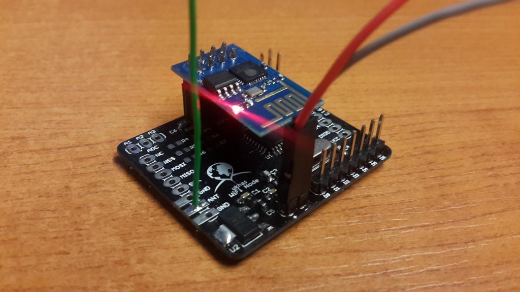
The system relies on packets being repeated between nodes, before hitting a “gateway” node which is connected to the internet. This may be a node connected to a PC, or a raspberry pi with an RFM69 radio. After seeing the ESP8266 popping up in various places, I decided to order a couple of modules and design a PCB for a simple AVR based wifi node.

qlbQJpC

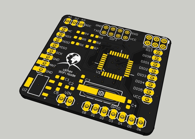
The PCB was very quick to put together and Phil’s repeater code had it working almost straight away.

node

I put together a library for sending HTTP POST requests to the ukhasnet server from an ESP8266 via AT commands. I updated my ESP chip with this firmware (File:V0.9.2.2_AT_Firmware.bin.zip from http://www.electrodragon.com/w/Wi07c /   Mirror) to reduce the speed down to 9600 baud. The chip does indeed work with WPA2 (which I was not expecting, possibly down to the firmware update)

The node has been running now for about 72 hours with no apparent problems 🙂

The ESP8266 Library, repeater/gateway code (credit to Phil) and PCB files are up at https://github.com/chrisstubbs93/ESP8266

The basic upload sketch looks something like this:

#include "ESP8266.h"
#include "wifiConfig.h" //this is where you need to set your SSID and Password
#define DST_IP "212.71.255.157" //ukhas.net 212.71.255.157
#define WIFI_EN 7 //CH_PD

ESP8266 esp8266 = ESP8266();

void setup()
{
  Serial.begin(9600); //Open serial communications 
  esp8266.initialise(Serial, WIFI_EN); //Pass it over to the ESP8266 class, along with the pin number to enable the module (CH_PD)
  while (!esp8266.resetModule()); //reset module until it is ready
  esp8266.tryConnectWifi(SSID, PASS);//connect to the wifi
  esp8266.singleConnectionMode(); //set the single connection mode
}

void loop()
{
  esp8266.uploadPacket(DST_IP, "your_data");
  delay(10000);
}


CHEAPO R3 boards

The new CHEAPO boards are here! I have soldered one up and all seems to be working perfectly! Here is a quick write up on the results.

IMAG1165

New board compared to old, looks much neater!

IMAG1193

Main components of CHEAPO3

IMAG1195 IMAG1197

Weight of CHEAPO3 with and without batteries

IMAG1201

Micro SD card installed (2GB seems like overkill for text logging!)

IMAG1202

Current consumption of board whilst acquiring GPS fix, writing to SD card and transmitting = 110.9mA. This will drop when the tracker gets a GPS fix and if the SD card is removed for long duration flights. I think I will have a go at optimizing the code and look into the power saving modes of the uBlox NEO-6

I am very happy with these boards and look forward to testing one in the air. Currently planning a possible pico launch on the 14/06/2013 (PM)

Self Etched SMD PCB (ATMega168PA Breakout) and programming

With tracker v2 complete and ready to fly. I decided to start work on v3 and I really wanted to try out a SMD board, properly etched in a PCB house.

PCB etching is super affordable now thanks to Hackvana. You can get some great quality boards for well under £20. But while I’m just messing about testing connections and code I thought i could put together a little breakout board. This will also help me practice my EAGLE skills and make sure I don’t miss any vital components on the final design.

I went for an interesting take on the tried and tested toner transfer method. This time I printed my design onto a sheet of paper lined with Kapton tape. The results were pretty good with outstanding toner density in the middle, but needed touching up a little around the edges.

Using kapton tape for toner transfer

Untitled

Untitled

In this tracker I will be using the RFM22B board from UPU’s store. It is an interesting transmitter working in the 430mhz range with an output of up to 100mw. The frequency can also be set in software which is a handy feature to avoid interference etc. The module communicates with the arduino over SPI.

I am also planning to solder a Ublox 6 chip and SMD antenna straight to the final board.

Its worth noting that this board is entirely 3.3v to work with the Ublox and RFM22B.

Turns out i missed the smoothing cap from the output of the 3v3 regulator and the 10k pullup on the reset pin. Glad this was only a practice board as they could be bug-soldered on.

Untitled

All soldered up with my great new iron. Fantastic price from the site recommended by Hix.

New soldering iron

Programming the ATMega168p was a bit of a pain. But here’s how i did it in the end:

The chip was initially programmed with the arduino bootloader using another arduino as an ISP programmer. To do this you need to ensure the chips signature matches what the arduino IDE is expecting. I ended up modifying the boards.txt entry for the pro mini 3.3v as it was the closest match to my setup. I simply appended a P onto the end of the MCU name.

Once the bootloader was is programmed you can then program the chip over TTL/serial using the arduino IDE’s upload button. However i found that the chips signature had changed and i needed to remove the P i added to boards.txt earlier.

Device signature can be checked with:

C:\WinAVR-20100110\bin\avrdude.exe -p Atmega168p -c avrisp -P com8 -b 19200

DIY UPS system *FEATURED*


Where I live, short power cuts are fairly frequent and can be very irritating. I have also wanted to experiment with CCTV for some time. After experimenting with test UPS systems using cheap inverters and old car batteries I decided to scale it up.
When homes have an alarm system installed it usually contains a backup battery in case of power failure. These batteries need to be replaced every few years to ensure the system performs correctly.
The waste batteries are usually sold to scrap dealers for their lead content, but alarm installers are usually happy to give/sell them to you for an incredibly low price. We have picked up 7AH batteries for less than 50p each.
The project was designed, tested and built by myself and Dom.

Check out the video:

A full how-to is availible at http://www.instructables.com/

I am proud to announce that he write up has been featured by the authors of Instructables on their homepage and has also made appearances on Hack A Day and Life Hacker. Gaining the project well over 10 thousand hits (not including hackaday)!

If you like the project please vote for us to win the Green Tech contest on Instructables.com (Vote button in header of page). Thanks!

ATTiny13 programming & servo data interception

After a digital out put from your hobby RC reciver on the cheap? You could glue a microswitch to a servo, or you could read those servo commands using an ATTiny in the Arduino programming enviroment. Then you can control your digital outputs according to the position being sent, without the need for a servo!

Before jumping straight into reading pulse signals. Lets get started out with the basics of the ATTiny13.

Programming:

Coding:

Testing:

For the full write up, please take a look at my instructable.

.NET Gadgeteer Gadgesketch

This is our end of UK pilot scheme competition entry from the Cambridge event back in January 2012.

Built and coded by myself (Chris Stubbs) and Dom Taglialvore, students of The Sandon School 6th Form.

The casing is made from vacuum formed acrylic and uses the standard FEZ Spider board.

Graphics are at first drawn to memory before being displayed on the screen to help prevent flickering.

The Gadgesketch lets you draw an image using the two potentiometers, then save it to an SD card to share.

Microsoft have taken the gadget over the USA to show their colleges an example of what students have been making.

Some clips from the Microsoft event can be seen below

Code: http://chris-stubbs.co.uk/Gadgeteer/EtchASketch%20Bitmaps.zip

Link: http://www.netmf.com/gadgeteer/forum/default.aspx?g=posts&t=2386

USB Robot *Instructables Robotics Week Winner*

We won! The prize is a “Robotics starter pack”. Will post the contents when i get it!
Update: The pack contained an Instructables badge and some stickers, 3 packs of “sugru” silicone putty and a copy of Autodesk SketchBook Pro! Thanks Instructables!
This instructible will describe the processes required to build a system for interfacing with a robot (and the basics of building a robot) around the velleman K8055 USB interface board (availible online or at maplins) The robot is built mostly from scraps i had at home and parts from a car breakers yard the whole project cost around £50 but will be much less if you have parts at home

Link: http://www.instructables.com/id/USB-Robot/