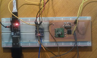
I have been working on a SMD tracker for a fair few weeks now, but today the last part fell into place making it ready for flight!
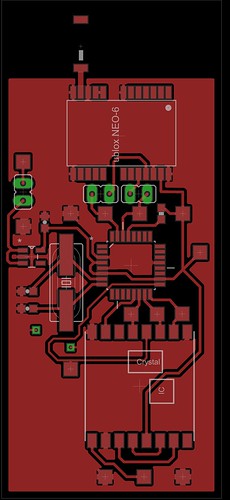
The PCB is the second board I have designed in EAGLE, only a few minor details weren’t quite right, but these could be rectified.
It is a topside only single layer board, making it possible to etch at home using the toner transfer method.
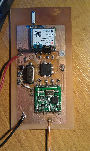
Once the board was etched I could solder on the TQFP ATMega168 micro controller, along with its crystal, loading capacitors and 10k pull up reset resistor (a feature I missed on the test breakout board design).
I chose to use the TITLV70032DDCR 3.3v low dropout regulator to power the board. It has a good current output of 200ma and very low drop out, allowing every last drop of power to be drained from the batteries. The thing is tiny, however the pin spacing is reasonable and proved quite nice to solder in comparison with the TQFP which was tricky and requires some practice.
The GPS module is a uBlox NEO-6. It is one of the few modules that continue to work at high altitude, however its software must be put into an airborne mode to allow this. The code on the ATmega waits until the GPS gets a valid fix before putting it into this mode, allowing for a faster time to first fix. The module has built in USB functionality along with lots of other features that go unused in this application. The communication between the GPS and ATmega is a hardware UART port. The GPS gets its signal using a surface mount JTI 1575AT43A40 Chip Antenna. I expected these tiny chips to get a very poor signal. However after leaving the board out to get its first ever fix for an hour or so, the chip can pick up a fix in a few minutes, and usually reports back 7 or 8 satellites.
I ran into problems with the exposed ground plane touching vias on the underside of the ublox. I removed that area of copper with a scalpel and soldering iron which solved the problem. I found the uBlox chip even more tricky to solder than the ATmega, the pins are small and easy to bridge to the metal casing so care should be taken. I actually missed a connection so i had trouble sending the flight mode command, as it simply didn’t make it into the GPS chip. A blob of solder connecting the GPS to the board solved that problem.
For a radio transmitter i am using a RFM22B module. These use the SPI protocol to communicate and have configurable frequency and power output via software. this makes every aspect of the transmission customizable, including shift. The module also has a built in receiver, making it possible for two way communication. However this is unused in my setup. The sending of RTTY is interrupt driven to free up the processor and give it time to handle the serial data. Also timing is more accurate for if i ever want to use a higher baud rate than 50.
If all goes according to plan I will be flying this tracker for testing and as a backup alongside my main payload (NSE) in April. Possibly Saturday the 13th depending on weather, updates to follow!


