With tracker v2 complete and ready to fly. I decided to start work on v3 and I really wanted to try out a SMD board, properly etched in a PCB house.
PCB etching is super affordable now thanks to Hackvana. You can get some great quality boards for well under £20. But while I’m just messing about testing connections and code I thought i could put together a little breakout board. This will also help me practice my EAGLE skills and make sure I don’t miss any vital components on the final design.
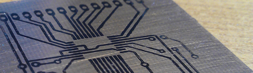
I went for an interesting take on the tried and tested toner transfer method. This time I printed my design onto a sheet of paper lined with Kapton tape. The results were pretty good with outstanding toner density in the middle, but needed touching up a little around the edges.


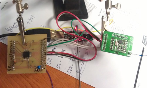
In this tracker I will be using the RFM22B board from UPU’s store. It is an interesting transmitter working in the 430mhz range with an output of up to 100mw. The frequency can also be set in software which is a handy feature to avoid interference etc. The module communicates with the arduino over SPI.
I am also planning to solder a Ublox 6 chip and SMD antenna straight to the final board.
Its worth noting that this board is entirely 3.3v to work with the Ublox and RFM22B.
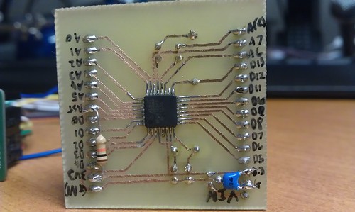
Turns out i missed the smoothing cap from the output of the 3v3 regulator and the 10k pullup on the reset pin. Glad this was only a practice board as they could be bug-soldered on.
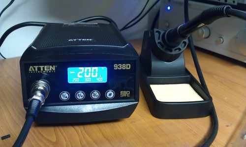
All soldered up with my great new iron. Fantastic price from the site recommended by Hix.
Programming the ATMega168p was a bit of a pain. But here’s how i did it in the end:
The chip was initially programmed with the arduino bootloader using another arduino as an ISP programmer. To do this you need to ensure the chips signature matches what the arduino IDE is expecting. I ended up modifying the boards.txt entry for the pro mini 3.3v as it was the closest match to my setup. I simply appended a P onto the end of the MCU name.
Once the bootloader was is programmed you can then program the chip over TTL/serial using the arduino IDE’s upload button. However i found that the chips signature had changed and i needed to remove the P i added to boards.txt earlier.
Device signature can be checked with:
C:\WinAVR-20100110\bin\avrdude.exe -p Atmega168p -c avrisp -P com8 -b 19200