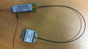
The NavSpark was an indiegogo campaign launched some time last year. It is essentially a GPS receiver with a 100MHz processor and 1024kb of flash memory. It also allows you to compile and upload code for it straight from the Arduino IDE. It comes in at a price of around 15 USD and a similar form factor to that of the Arduino Nano.
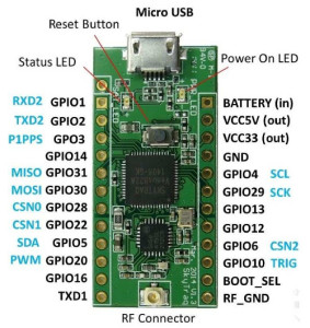
NavSpark board pinout.
After many months of waiting and a few badly translated Chinese update emails, my two preorder NavSpark boards arrived! They sat around on my desk for a fair few weeks before I decided to sit down and crack on with turning them into trackers.
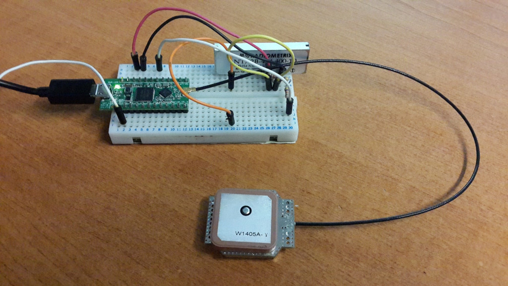
The first step was to set one up on some breadboard with an NTX2B and a resistor network to set the shift, then toggle a GPIO pin on and off to produce the mark/space tones required for RTTY.
It took a bit of faffing around to actually get code onto it. Sometimes it will not allow you to upload, and you have to short BOOT_SEL to GND to restore the working bootloader from ROM, then try again. But I eventually had a program that was toggling pin 12 on and off.
Putting “GnssConf.init();” in “setup()” initializes the GNSS receiver and causes “task_called_after_GNSS_update()” to run. Inside this function its remarkably easy to get all the GPS data your tracker might want, without the need to mess around with any NMEA parsing.
void task_called_after_GNSS_update(void)
{
GnssInfo.update();
gps_hour = GnssInfo.time.hour();
gps_min = GnssInfo.time.minute();
gps_sec = GnssInfo.time.second();lat = GnssInfo.location.latitude();
lng = GnssInfo.location.longitude();alt = GnssInfo.altitude.meters();
gps_sats = GnssInfo.satellites.numGPSInUse(NULL);
gln_sats = GnssInfo.satellites.numGLNInUse(NULL);}
Then came the challenge to tackle the timing of sending RTTY. Luckily it turns out the Navspark has a few timers to use with millisecond precision [page 80 TIMER]
uint8_t tmr0 = Timer0.every(20, tmr_task);
Its then as simple as sticking Anthony Stirk’s great little Interrupt based RTTY script inside the tmr_task() function. With some minimal modification to write the GPIO pin high/low.
Check out the code here.
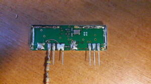
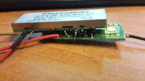
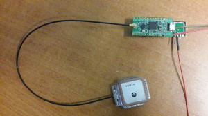
I soldered a couple of 4k2 0603 resistors between VCC and DATA, then DATA and GND on the NTX2, also shorting VCC and EN. I then soldered a 47K and 10K resistor in series to the DATA pin, then connected the other end to our NavSpark’s GPIO pin. You can solder the NavSpark board pretty much straight on top of the NTX2B, but its probably a good idea to add some insulation (kapton tape) between the two. The NTX2 GND is connected to the GND on the board, and VCC to the 3.3v regulated output.
Overall I found the NavSpark hardware very easy to work with, and the coding perhaps even easier than a normal Arduino/uBlox.NTX2 tracker, mainly due to the lack of requirement for a NMEA parser. The NavSpark documentation is a little sparse and badly translated, however everything you need programming wise can be found here. The performance of the GPS in terms of time to first fix is very good, getting a time fix after the first sentence, and a position fix after 4/5 sentences. Once it had aquired a fix and with the NTX2B running, with the supply voltage set at 5.6V and fed to the battery input, the tracker was using about 65mA current.
Would I recommend the NavSpark over an AVR/uBlox based tracker?
I’d certainly consider it! There is probably far more information out there in the AVR world, but if you are just making a simple RTTY tracker then it is certainly a viable option. Just wait for the flight test in the next month or so before rushing out to launch one!
Speaking of flight, what about the COCOM GPS limit?
According to SkyTraq the GPS will only shutdown if 18km altitude AND 1000km/h velocity are exceed simultaneously, meaning it should well be suitable for HAB use.

