NSE1 High Altitude Balloon Launch

The Launch

The morning started off a little frosty as we packed kit into the car and ran final tests on the payloads. NSE was performing normally but CHEAPO would not parse on Habitat. This was down to incorrect padding of the time (it was being sent at “64500” instead of “064500”). After a hotfix being applied to Habitat (Thanks DanielRichman) we were set up and ready for business.

8665483537_6a20713a5f_z[1]

The payloads were tied together and the balloon filled, before being released.

OLYMPUS DIGITAL CAMERA

The balloon then climbed at an average of 4.3m/s to 27500m, before bursting and falling back to earth at an astonishing rate.

NSE alt-time graph

The Recovery

We drove to the landing site near Burwash and looked around as the balloon flew right above our heads on the tracker. I saw the faint shadow of the parachute on the horizon and headed across the town to the opposite side of the Forrest it was expected to land next to. After a few minutes of walking around with the radio we knew we were close. After speaking to one of the locals they let us climb over their fence to retrieve the payload from their field.

IMAG1085

Picture1

Post flight analysis

The balloon burst was predicted to be around 21000m so we were surprised and slightly worried as it carried on climbing all the way to 27000m. This was probably due to the balloon being slightly under filled as our average ascent rate was below target.

Cheapo’s GPS code worked fine. Maintaining a fix of 9 satellites throughout the flight. The only software bug being the padding on the time field, which has now been resolved so should not pose a problem on future flights. Cheapo only had a couple of receivers over its flight, who reported a very poor signal from it. I believe this was due to the radials of the 1/4 wave antenna being bent over the driven element. The next flight will use straws to prevent the radials from sagging or bending out of shape.

NSE’s signal was perfect, with about 20 simultaneous receivers at one point. The antenna reinforcing (straws) paid off and the payload could be heard from a fair distance away on landing. The path on the tracker appeared to jump to 0,0 at one point. Upon analyzing a data export from habitat that evening I found that the payload was having difficulty getting strings from the GPS module on several occasions, reporting back 0 connected satellites and falling back to the last know coordinates. This was most likely down to using Software Serial.

Temperature data was collected using the AtMega168’s internal sensor. The payload got down to -20C on its descent with no problems

tempgraph - Copy

The TK102 tracker we flew as backup did work in the end, however was probably not worth its weight as the firmware on it is horrible and proves very unreliable.

Overall the flight was a success, and I am very happy we managed to recover it okay. We are hoping to fly again with a better camera soon, and also try and fly CHEAPO on its own, either as a floater or with a pico balloon.


CHEAPO budget self etched SMD GPS tracker

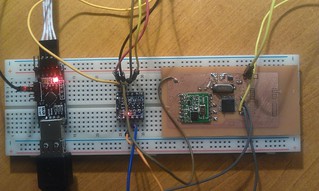
I have been working on a SMD tracker for a fair few weeks now, but today the last part fell into place making it ready for flight!

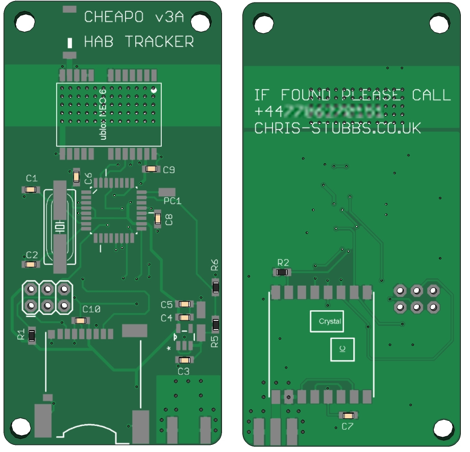
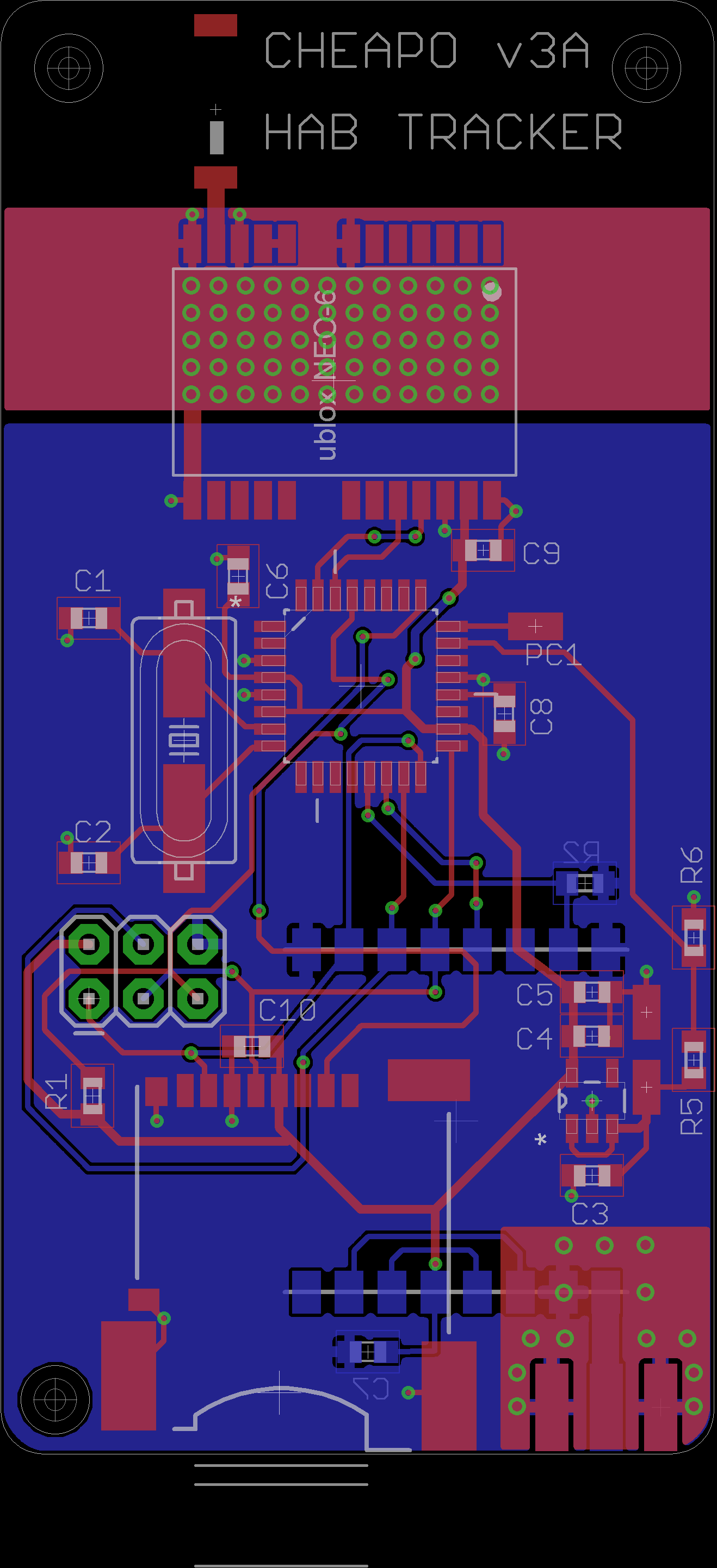
The PCB is the second board I have designed in EAGLE, only a few minor details weren’t quite right, but these could be rectified.
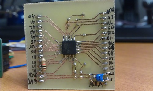
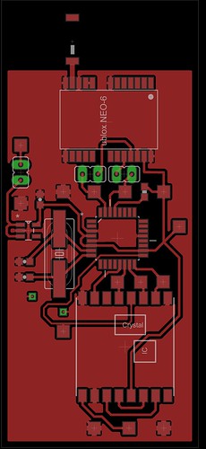
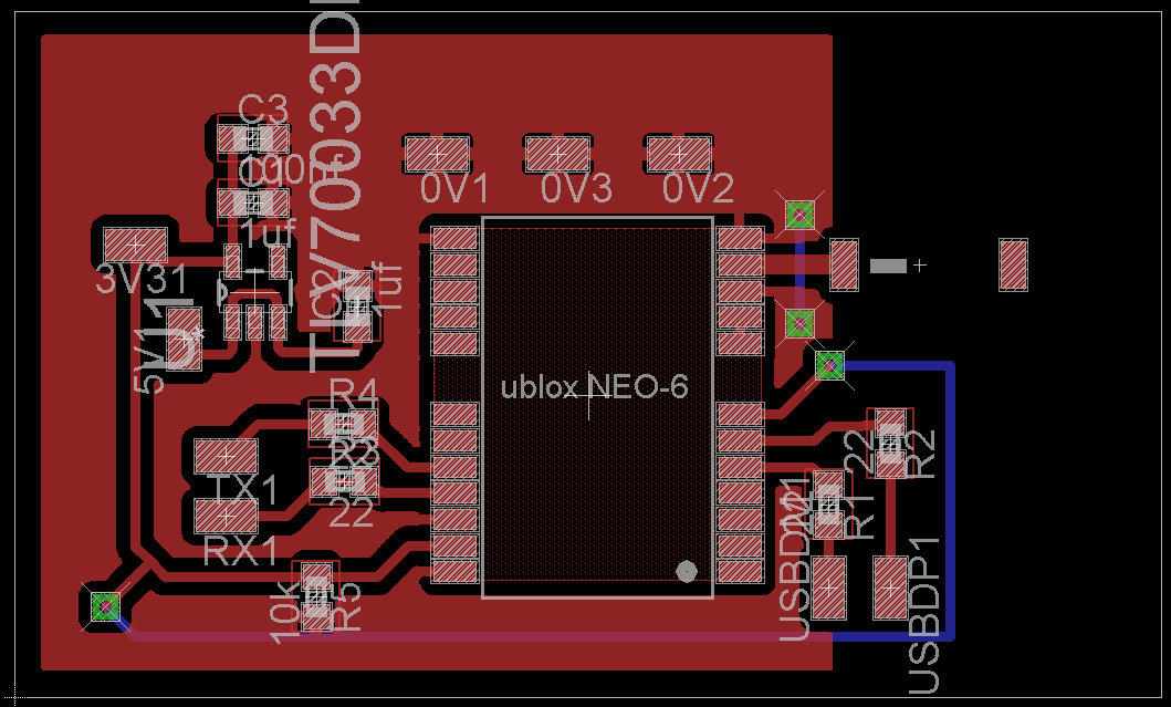
It is a topside only single layer board, making it possible to etch at home using the toner transfer method.

$$CHEAPO Pico Board Rendering

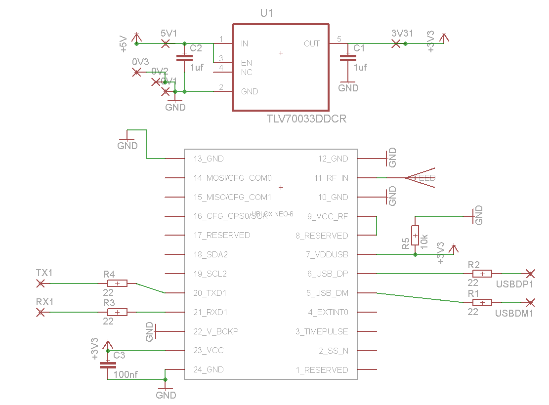
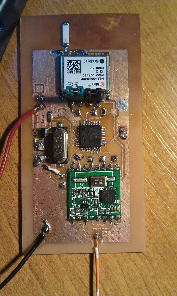
Once the board was etched I could solder on the TQFP ATMega168 micro controller, along with its crystal, loading capacitors and 10k pull up reset resistor (a feature I missed on the test breakout board design).

Untitled

I chose to use the TITLV70032DDCR 3.3v low dropout regulator to power the board. It has a good current output of 200ma and very low drop out, allowing every last drop of power to be drained from the batteries. The thing is tiny, however the pin spacing is reasonable and proved quite nice to solder in comparison with the TQFP which was tricky and requires some practice.

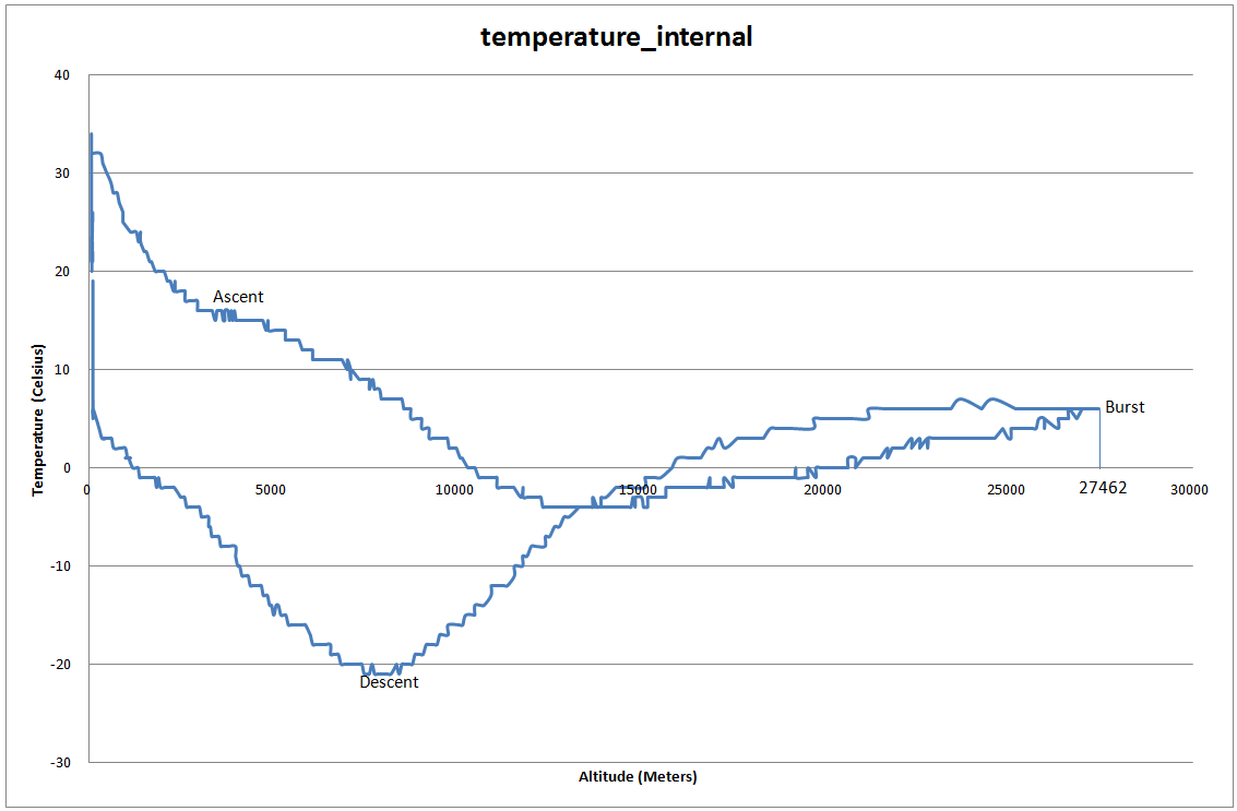
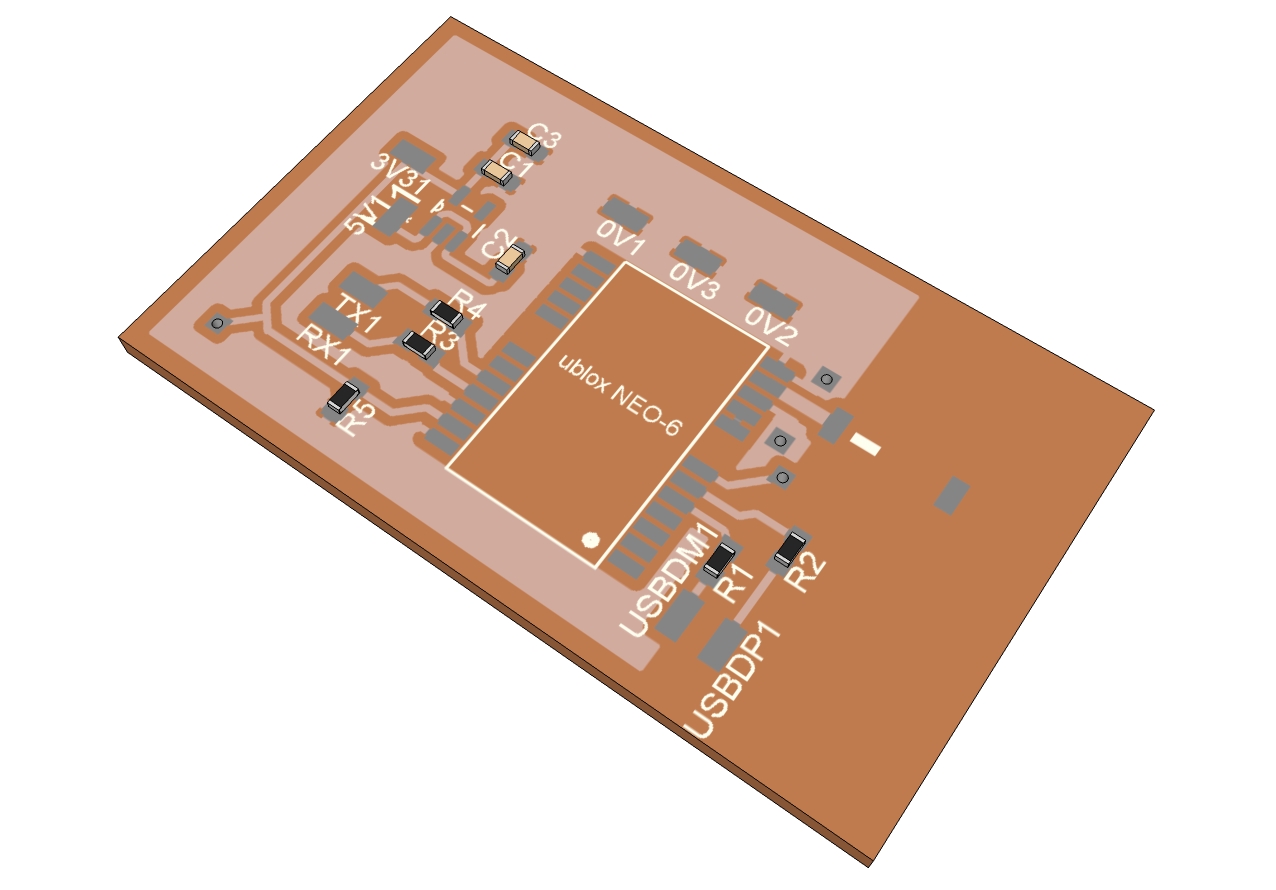
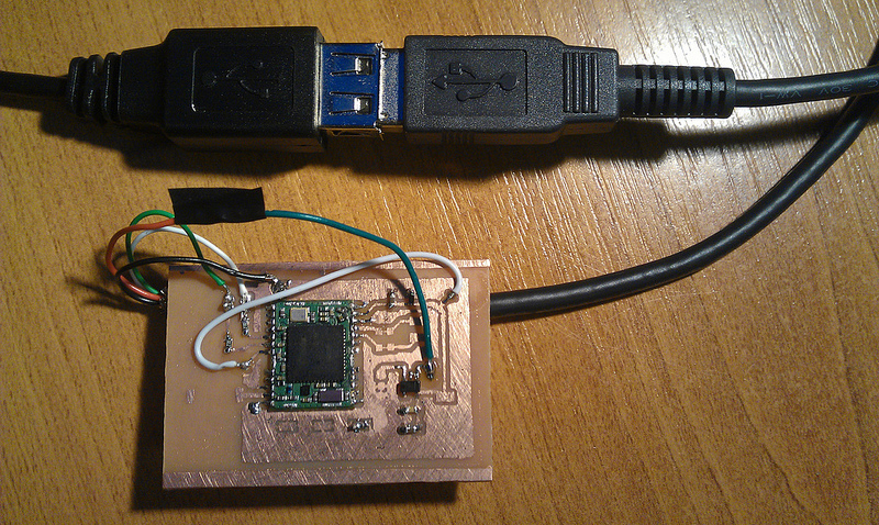
The GPS module is a uBlox NEO-6. It is one of the few modules that continue to work at high altitude, however its software must be put into an airborne mode to allow this. The code on the ATmega waits until the GPS gets a valid fix before putting it into this mode, allowing for a faster time to first fix. The module has built in USB functionality along with lots of other features that go unused in this application. The communication between the GPS and ATmega is a hardware UART port. The GPS gets its signal using a surface mount JTI 1575AT43A40 Chip Antenna. I expected these tiny chips to get a very poor signal. However after leaving the board out to get its first ever fix for an hour or so, the chip can pick up a fix in a few minutes, and usually reports back 7 or 8 satellites.

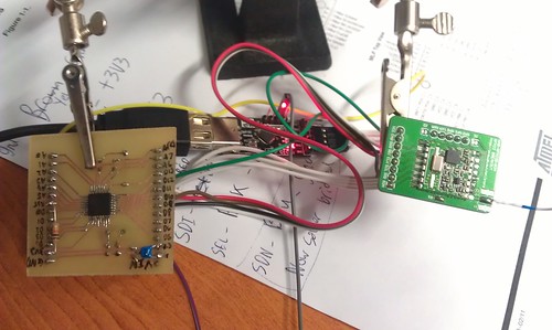
I ran into problems with the exposed ground plane touching vias on the underside of the ublox. I removed that area of copper with a scalpel and soldering iron which solved the problem. I found the uBlox chip even more tricky to solder than the ATmega, the pins are small and easy to bridge to the metal casing so care should be taken. I actually missed a connection so i had trouble sending the flight mode command, as it simply didn’t make it into the GPS chip. A blob of solder connecting the GPS to the board solved that problem.

For a radio transmitter i am using a RFM22B module. These use the SPI protocol to communicate and have configurable frequency and power output via software. this makes every aspect of the transmission customizable, including shift. The module also has a built in receiver, making it possible for two way communication. However this is unused in my setup. The sending of RTTY is interrupt driven to free up the processor and give it time to handle the serial data. Also timing is more accurate for if i ever want to use a higher baud rate than 50.

Untitled

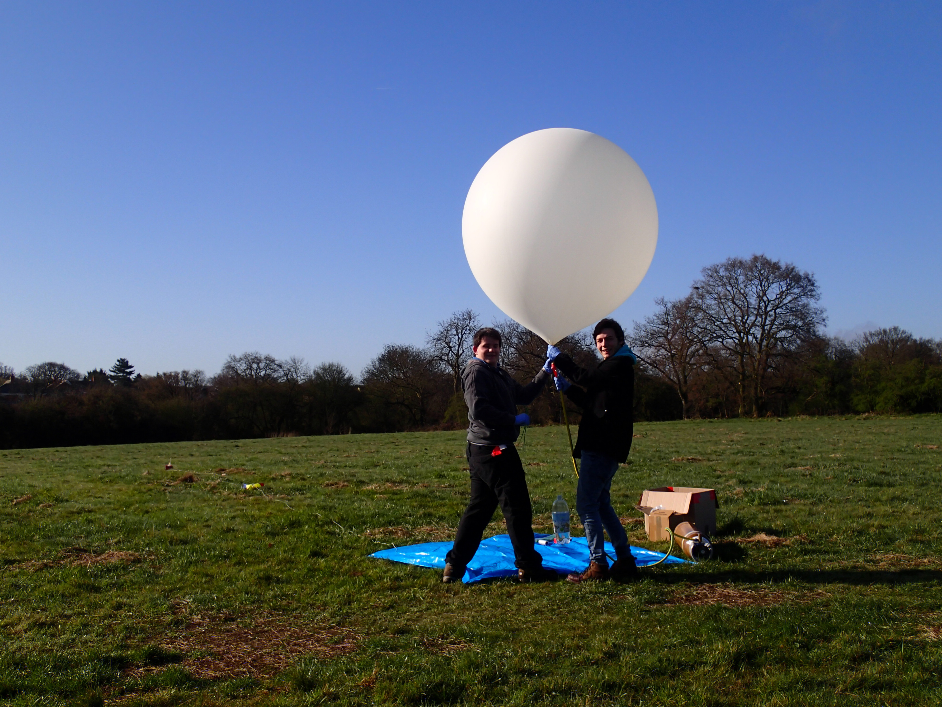
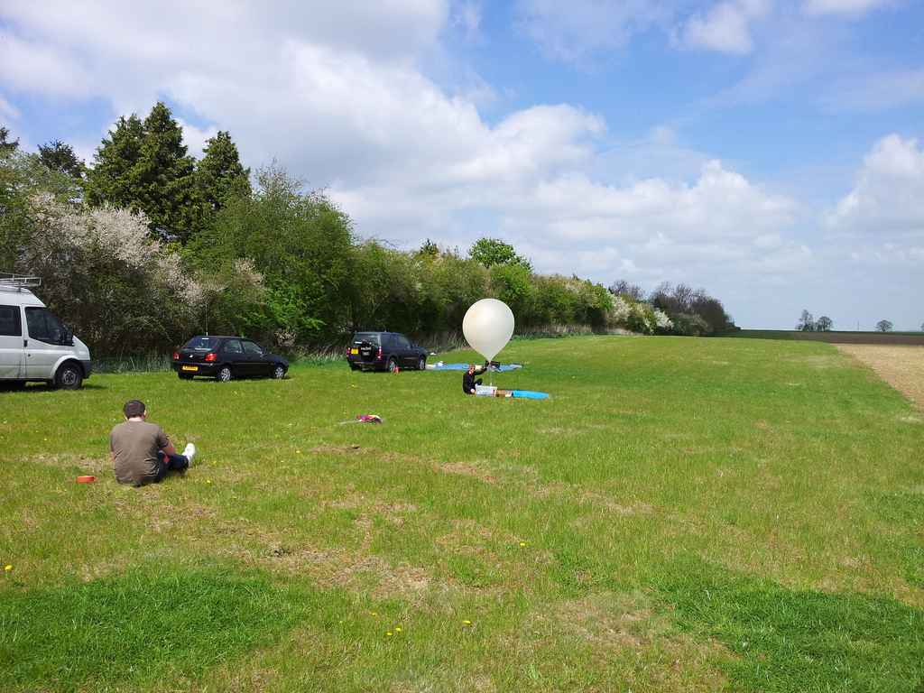
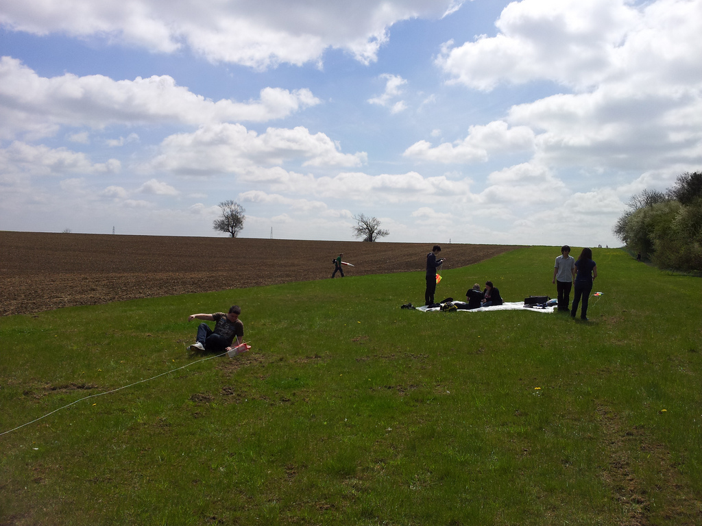
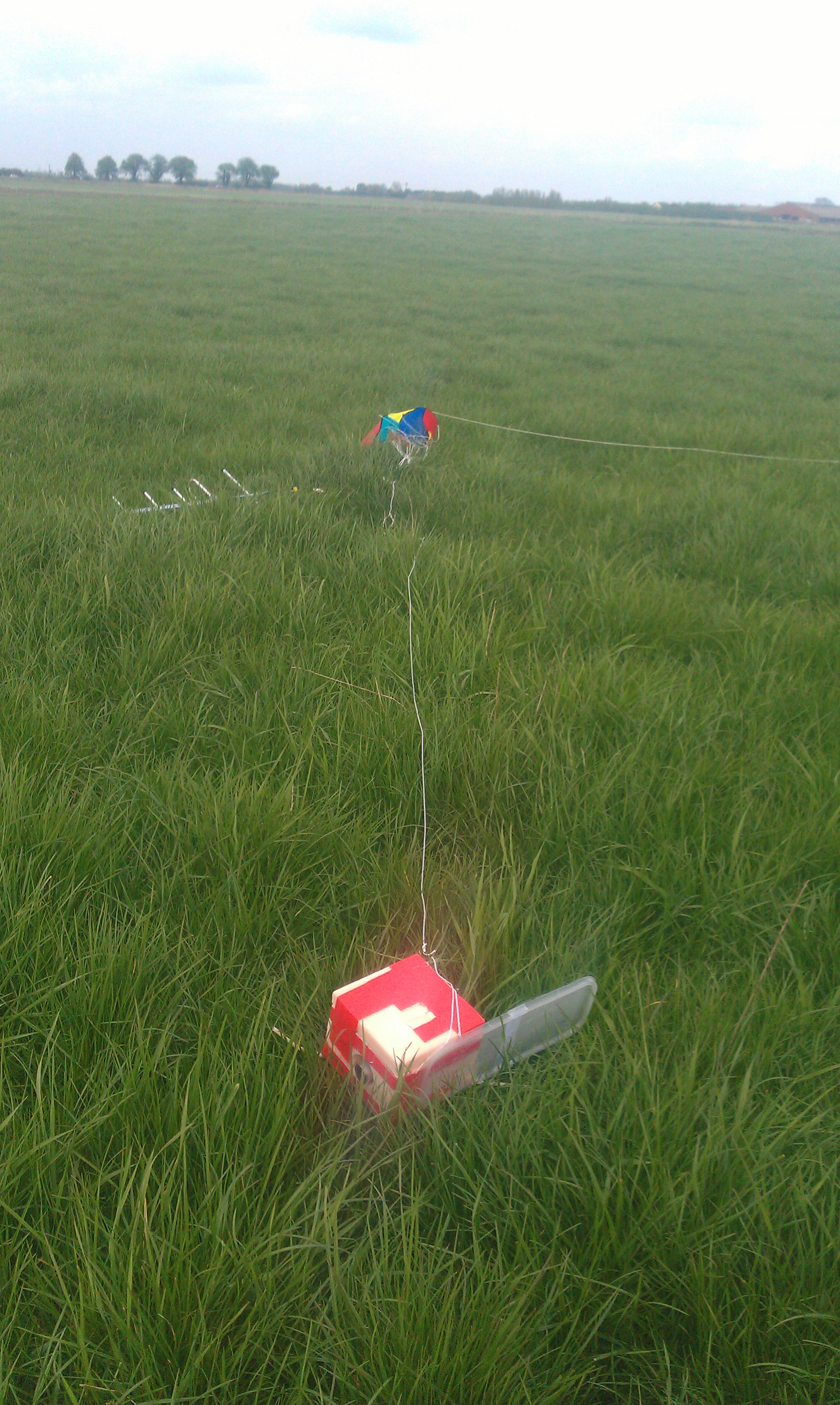
If all goes according to plan I will be flying this tracker for testing and as a backup alongside my main payload (NSE) in April. Possibly Saturday the 13th depending on weather, updates to follow!

NSE1 Launch Planning (April 2013)

I have heard back from the CAA that the preliminary approval will be issued tomorrow, which is fantastic news! The proper permission should be issued closer to our launch window in April (every weekend, in the hope that one will be good to launch in).

In the meantime I have been working on a SMD tracker board that, if finished in time, will fly as backup on the same flight. The objective of the tracker is to make a board for domlins pico flights as cheap as possible. Hence the payload name $$CHEAPO.

Untitled

$$CHEAPO Pico Board Rendering

NSE1’s flight code has been adjusted to enable flight mode as soon as it gets a GPS fix. This is because the uBlox chip seems to get a fix much faster if left in default mode. Once the fix has been acquired it sends the command to switch to airborne flight mode.

NSE1 outputs telemetry strings on 434.650(ish)MHz at 50 baud, 7 bit ascii, 2 stop bits and 350Hz carrier shift. The format is as follows:

$$NSE,message_ID,time,lng,lat,altitude,satelites,battery,flight_mode,temp_internal*99A6

Self Etched SMD PCB (ATMega168PA Breakout) and programming

With tracker v2 complete and ready to fly. I decided to start work on v3 and I really wanted to try out a SMD board, properly etched in a PCB house.

PCB etching is super affordable now thanks to Hackvana. You can get some great quality boards for well under £20. But while I’m just messing about testing connections and code I thought i could put together a little breakout board. This will also help me practice my EAGLE skills and make sure I don’t miss any vital components on the final design.

I went for an interesting take on the tried and tested toner transfer method. This time I printed my design onto a sheet of paper lined with Kapton tape. The results were pretty good with outstanding toner density in the middle, but needed touching up a little around the edges.

Using kapton tape for toner transfer

Untitled

Untitled

In this tracker I will be using the RFM22B board from UPU’s store. It is an interesting transmitter working in the 430mhz range with an output of up to 100mw. The frequency can also be set in software which is a handy feature to avoid interference etc. The module communicates with the arduino over SPI.

I am also planning to solder a Ublox 6 chip and SMD antenna straight to the final board.

Its worth noting that this board is entirely 3.3v to work with the Ublox and RFM22B.

Turns out i missed the smoothing cap from the output of the 3v3 regulator and the 10k pullup on the reset pin. Glad this was only a practice board as they could be bug-soldered on.

Untitled

All soldered up with my great new iron. Fantastic price from the site recommended by Hix.

New soldering iron

Programming the ATMega168p was a bit of a pain. But here’s how i did it in the end:

The chip was initially programmed with the arduino bootloader using another arduino as an ISP programmer. To do this you need to ensure the chips signature matches what the arduino IDE is expecting. I ended up modifying the boards.txt entry for the pro mini 3.3v as it was the closest match to my setup. I simply appended a P onto the end of the MCU name.

Once the bootloader was is programmed you can then program the chip over TTL/serial using the arduino IDE’s upload button. However i found that the chips signature had changed and i needed to remove the P i added to boards.txt earlier.

Device signature can be checked with:

C:\WinAVR-20100110\bin\avrdude.exe -p Atmega168p -c avrisp -P com8 -b 19200

CUSF hourly predictor install

A few days ago i was introduced to the hourly predictor by the guys on #highaltitude IRC.
It is a handy lump of software that is built around the normal balloon flight predictor, however it runs a forecast for a launch at each hour of the next week.
This allows you to pick out the best date/time to launch.
The setup was reasonable to understand but the documentation pretty much consisted of a list of terminal commands.
I have put together a video outlining how to set this up in a vmware player virtual machine, going through each command and what (I think) it does.

If you find the video below useful, or have any other questions please leave me a message or find me on IRC (chrisstubbs) #highaltitude

I am slowly uploading a copy of the VM for people to download… so that will appear here shortly…. but might not work properly on other machines!

Instructions: cusf_install


NSE1 – Tracker v0.2

This is the second version of my Ublox6 NTX2 ATMega328 tracker.

It is built around the TinyGPS library and reports back its GPS Time, Coordinates, Battery voltage and Temperature over a 434.65Mhz RTTY radio link.

Tracker Specification:
Chip: Atmel ATMega328P-PU
Chip bootloader: Arduino
PCB Design: ExpressPCB
PCB Etching: Toner Transfer
Voltage Measurement: Voltage divider and 1.1v internal analog reference
5V Regulator: TS2950CT low drop out regulator
Transmission mode: RTTY, 50 Baud, 425mhz shift, 7-bit ASCII, no parity with 2 stop bits on 434.650MHZ
Antenna: 1/4 wave with 4 radials
Battery: 4x Energizer Lithium AA cells
Radio Module: Radiometrix NTX2 (From HabSupplies)
GPS Module: Ublox 6 (From HabSupplies)

Find the highest point in a given radius

I have recently built a quick tool using the google maps API to find the highest point within a radius of a given coordinate.
The tool can be found at http://chris-stubbs.co.uk/extras/maps/alt/

Gregory has since made a much prettier version. Check it out: http://gregoryalary.xyz/apex/ https://github.com/gregoryalary/summit-finderhttps://gregoryalary.github.io/summit-finder/

Other tools include the Solwise elevation tool and HeyWhatsThat profiler.