EMF Camp 2014 – Habville

On the 29th August – 1st September, I joined over 1000 other campers at Electromagnetic Field camp in Milton Keynes. Said field was equipped with mains power and high speed internet, which allowed them to host some great workshops, talks and demos including on site laser cutting! I camped with a few other UKHAS members in our “villiage” aptly named “HABVille”

14934548189_3969ae772d_o

We ran a couple of launches, which had a pretty good turn out of interested people who arrived on time to watch. However with tradition the launches were vastly delayed as trackers were still being assembled and programmed.

14934576130_fecbdb1460_b

The first of these was one of my Cheapo boards on a foil balloon, which sadly didn’t quite manage to enter a float, but did cross the channel. The second was a JOEY board running both Matt’s TurboHAB and RTTY, a UKHASnet node, and Richard’s Bristol University SEDS tracker. All 3 of these payloads were carefully strung under a 100g balloon and filled with all the helium we could get our hands on.

P1010849 (Large) P1010850 (Large) P1010851 (Large)

One of the other perks of the camp were the badges, which unfortunately weren’t quite ready to hand out as soon as the gates opened. The radio network for delivering weather and schedule updates (an awesome idea) was pretty ropey too. But provided some excitement when someones badge started working on it.

15271518645_d1c9a8c74e_b

We also spent a bit of time down at The Grid, an interactive light installation put together by Adam Greig and David Turner. Which attracted a lot of attention when it sprung to life at night, with people drunkenly charging around in amazement as the poles lit up around them. Adam and David clearly put an awful lot of work into this project, which they discussed in their talk. I shot some footage on my unfortunately gimbal-less hex.

NottingHack brought along their BarBot, which happily served me an interesting concoction of alcohol.

CHDK/SPARK/CHEAPO Launch – Thu 04/09/14

A couple of weeks ago I launched a few projects I had been working on over the last year or so on a 1200g Pawan latex balloon. These projects included:

The CHDK rig from the conference last year, sending live 600 baud SSDV images encoded straight on the camera. A Navspark based tracker. And A Cheapo Mini flying backup.

I did plan to launch a nasty looking GPS UKHASnet node, but the AVR got stubborn just as we were about to launch and refused to accept any new code.

The launch went off pretty much without a hitch and roughly on schedule, with some much appreciated help from Lewis.

20140904_165702

Launch video to be added at some point..

Things seemed to be going according to plan, until SPARK hit about 19KM and decided it had enough. The altitude stopped ascending and the GPS wandered off course, shortly followed by the GLONASS satellites dropping down to 0 and GPS to 3. I posted my results to the navspark forum, but their only theory was that it couldn’t handle the temperature. I’m not exactly sold on this, as it seemed to die at exactly 19km (hey, that could be a coincidence) and the board should feature a TCXO. Perhaps some modes need changing. I will repeat this experiment sooner or later.

Just as the flight started to get interesting, cheapo also decided today was not a good day for HAB. The battery voltage plummeted as the temperature dropped and silence fell. Luckily on the descent things started to warm up, increasing the battery voltage and bringing the tracker back in time to track the landing. I have not seen a lithium battery drop quite this much in voltage before, so I suspect I had a bad cell.

Surprisingly the part I thought most likely to fail actually performed perfectly! The camera sent down SSDV images throughout its flight, with no packets being missed! A great success and a final thank you to Reyalp from CHDK and Phil Heron for their help with the project. The next step will be to implement the whole thing again on a more modern camera with GPS, but I think a well earned break is due first!

SSDV Live Images

The flight photos will appear here at some point, along with the 15gb of gopro footage…


NavSpark based RTTY tracker

The NavSpark was an indiegogo campaign launched some time last year. It is essentially a GPS receiver with a 100MHz  processor and 1024kb of flash memory. It also allows you to compile and upload code for it straight from the Arduino IDE. It comes in at a price of around 15 USD and a similar form factor to that of the Arduino Nano.

pinout1

NavSpark board pinout.

After many months of waiting and a few badly translated Chinese update emails, my two preorder NavSpark boards arrived! They sat around on my desk for a fair few weeks before I decided to sit down and crack on with turning them into trackers.

The first step was to set one up on some breadboard with an NTX2B and a resistor network to set the shift, then toggle a GPIO pin on and off to produce the mark/space tones required for RTTY.

14586862591_044677e949_h

NavSpark board and NTX2B on breadboard

It took a bit of faffing around to actually get code onto it. Sometimes it will not allow you to upload, and you have to short BOOT_SEL to GND to restore the working bootloader from ROM, then try again. But I eventually had a program that was toggling pin 12 on and off.

Putting “GnssConf.init();” in “setup()” initializes the GNSS receiver and causes “task_called_after_GNSS_update()” to run. Inside this function its remarkably easy to get all the GPS data your tracker might want, without the need to mess around with any NMEA parsing.

void task_called_after_GNSS_update(void)
{
GnssInfo.update();
gps_hour = GnssInfo.time.hour();
gps_min = GnssInfo.time.minute();
gps_sec = GnssInfo.time.second();

lat = GnssInfo.location.latitude();
lng = GnssInfo.location.longitude();

alt = GnssInfo.altitude.meters();

gps_sats = GnssInfo.satellites.numGPSInUse(NULL);
gln_sats = GnssInfo.satellites.numGLNInUse(NULL);

}

Then came the challenge to tackle the timing of sending RTTY. Luckily it turns out the Navspark has a few timers to use with millisecond precision [page 80 TIMER]

uint8_t tmr0 = Timer0.every(20, tmr_task);

Its then as simple as sticking Anthony Stirk’s great little Interrupt based RTTY script inside the tmr_task() function. With some minimal modification to write the GPIO pin high/low.

Check out the code here.

I soldered a couple of 4k2 0603 resistors between VCC and DATA, then DATA and GND on the NTX2, also shorting VCC and EN. I then soldered a 47K and 10K resistor in series to the DATA pin, then connected the other end to our NavSpark’s GPIO pin. You can solder the NavSpark board pretty much straight on top of the NTX2B, but its probably a good idea to add some insulation (kapton tape) between the two. The NTX2 GND is connected to the GND on the board, and VCC to the 3.3v regulated output.

20140715_211323

NTX2B with resistors.

20140715_230157

NTX2B / NavSpark sandwich.

20140715_215626

NavSpark side up, showing antenna.

20140715_215645

NTX2B side up, showing antenna.

Sitting on my desk, still managed a time fix.

Sitting on my desk, still managed a time fix.

Overall I found the NavSpark hardware very easy to work with, and the coding perhaps even easier than a normal Arduino/uBlox.NTX2 tracker, mainly due to the lack of requirement for a NMEA parser. The NavSpark documentation is a little sparse and badly translated, however everything you need programming wise can be found here. The performance of the GPS in terms of time to first fix is very good, getting a time fix after the first sentence, and a position fix after 4/5 sentences. Once it had aquired a fix and with the NTX2B running, with the supply voltage set at 5.6V and fed to the battery input, the tracker was using about 65mA current.

Would I recommend the NavSpark over an AVR/uBlox based tracker?

I’d certainly consider it! There is probably far more information out there in the AVR world, but if you are just making a simple RTTY tracker then it is certainly a viable option. Just wait for the flight test in the next month or so before rushing out to launch one!

Speaking of flight, what about the COCOM GPS limit?

According to SkyTraq the GPS will only shutdown if 18km altitude AND 1000km/h velocity are exceed simultaneously, meaning it should well be suitable for HAB use.

CARS High Altitude Balloon Launch 01 July 2014

Chris Stubbs M6EDF launched a High Altitude Balloon from the CARS club night at the Oaklands Museum on the 1st of July 2014. This page contains information on the flight of CARS1 for those interested in tracking the flight.

The flight started at 19:50BST on Tuesday.

  • 19:50BST – Flight launched from Oaklands Museum, Chelmsford
  • 23:05BST – The balloon has passed Maidstone, heading South, floating at 4,600 metres
  • 00:00BST – The balloon left the East Sussex coast, floating over the English Channel towards France
  • 02:50BST – This was the last packet received here in Southend, showing CARS1 halfway across the English Channel heading to France
  • 06:45BST on Wednesday morning, the balloon was still in flight, over France at 5,400metres, but no packets have been received as of 0720BST. Voltage of the single 1.5 volt battery has dropped to 0.7V, so CARS1 may be flying but no longer be transmitting.

The Flightpath

To see where “CARS1″ is, go to http://spacenear.us/tracker/?filter=CARS1

CARS1 / Cheapo 13 as of 23:05 01 July 2014

Last reported position of CARS1 as of 0645BST 02 July 2014

Altitude achieved by CARS1 as of 0645BST 02 July 2014


The Frequency

As of 23:05 local, I’m tracking a very strong signal on 434.293MHz USB – Stations tracking at this time include G6GZH, G0TDJ, M0JCU, PB0AHX, G6SUQ, M6EDF, F5APQ, M0PSX, F1OIL, G4MYS, G7OGX, G8KNN-1, G8KNN, G8JZT, G0WXI, ASTRA_J, G0CXW_2, G8APZ

Receiving CARS1 data from Southend-on-Sea

The last packet received here in Southend-on-Sea was at 0354BST, but it continued to be tracked by others beyond that point.

Chat with Chris

As of 23:00, Chris M6EDF is in the High Altitude chatroom: webchat.freenode.net/?channels=highaltitude – Just made contact to thank Chris for his talk and to confirm he’s very audible in Southend-on-Sea

High Altitude chatroom - chatting to Chris M6EDF

CARS-1 Launch Video

A short video showing the launch and the tracking of this HAB flight:


CARS-1 Photos

Pictures of the launch and presentation 01 July 2014 at Oaklands Museum, for the Chelmsford Amateur Radio Society July Club Night…

CARS1, released by Chris M6EDF at the CARS club night

Watching the balloon head off at Oaklands Museum 01 July 2014

CARS1 on its way, one minute after take-off

Chris M6EDF starting his presentation at CARS

The CARS1 balloon and payload

Chris, showing the audience where the balloon had reached after 15 minutes of flight

The audience at the Chelmsford Amateur Radio Society's July meeting

Chris M6EDF and John G1UZD, with CARS1 in the background on-screen

The CARS1 balloon and payload


For more on this, see CARS-1 High Altitude Balloon Video


Article by Pete M0PSX – http://www.essexham.co.uk/news/cars1-hab.html

Cheapo “Micro” (v5) is here

I received the boards for my latest cheapo design revision the other week. The design is very simalar to the previous version, but I am now using the uBlox MAX-7 because of its lower power consumption. I have also shrunk the boards down a little.
The funny arrangement at the top for the GPS antenna is an experiment to see how well chip antennas perform horizontally. So far I have only tested the board in its standard configuration and it all checks out okay! Test flight to follow soon.

Untitled
Untitled-1

On a side note I also put together a very crude ICSP jig using pogo pins and a clothes peg to avoid having to solder a header onto each board. The alignment isn’t great but does the job.

20140308_224135

F550/APM based Hexacopter build

Part 1 – BOM and frame

Having looked into building a quadcopter some time in the summer, I was put off by price. But after now seeing a couple in person and the amazing footage they can produce, I decided to give the world of multirotors a whirl!

I got the idea of a hexacopter into my head simply because if they have two more blades they must be 50% more awesome? Right?

I have not even started the build yet, but just researching and ordering the parts is making me think they are just 50% more money… We will have to wait for the end result on that one.

After a quick chat to some other multirotor guys on IRC, I picked up a cheap Hubsan X4 with some spare nectar points to practice my crashing. This was probably worth the money as flying a multirotor takes a little bit of getting used to after flying cheap helicopters.

This is what I have ordered so far for the build (Pretty much up to date):

Part Quantity Price (GPB each) Description
H550 V2 Frame 2 13.60 Hex frame (+1 spare of everything)
NTM Prop Drive 28-26 1000KV Motors 7 10.55 1000rpm/volt motors (+1 spare)
Turnigy plush 30A ESC 7 8.67 Hobbyking own brand ESC (+1 spare)
NTM Prop Drive 28 Series acc pack 7 1.25 Motor and prop mounts (+1 spare)
GWS 9×5 Propellers 10 2.50 3 CW and 3 CCW props (+ spare sets, you will need them!)
Sevo leads (10pk) 1 1.68 These look like extenders and the APM comes with connecting leads, so not sure why I got them!
HKPilot Mega 2.5 1 50.02 Ardupilot mega clone (remember to stick foam on the barometer!)
uBlox NEO-6 GPS 1 11.87 I already had a MAX-6 breakout, but finding the lead to plug it into the APM was hassle, plus this one has a battery backup.
Turnigy 9X transmitter/receiver 1 35.52 Very cheap, I fancied the 9XR but adding the TX and RX modules was getting expensive. Do that if you have the cash. LCD upgrade.
PolyMax 3.5mm connectors 2 1.21 Connect motors to ESC’s
HXT 4mm connectors 1 2.79 Connect battery to frame’s power distributor.
Turnigy 5000mAh 4S 25C Lipo 2 23.52 Should last just under 10mins without load.
HKPilot power module 1 11.59 Seems a bit steep for a 5v PSU, plus we are going to demolish that 90A current limit at peak. But oh well…
Lipo low voltage alarm 1 1.37 Cheap and better than a forced landing (crash)
HKPilot mounting box 1 3.78 At 3.78 it beats 3D printing one.
Prop balancer 1 0.93 Someone said this was a good idea. at 93p who cares!
Telemetry Kit 1 19.79 Will be handy to find the thing + debug if (when) it crashes
Lipo Charger 1 15.17 This would be about £100 knowing my local hobby shop…
Lithium Polymer Charge Pack 1 2.18
Turnigy Pure-Silicone Wire 10AWG 2 2.06 Black and red
Anti-Vibration foam 1 0.97 This was great for mounting the APM (used 4x 10x10mm squares). Can also be stuffed in anti vibration bulbs to stiffen them up.
Rhino 2620mAh 3S Transmitter Lipoly 1 10.56
Crappy landing gear 1 14.90 Dont buy this. Please. Get something better.
Gimbal 1 30.99 Basic gimbal with motors.
EvvGC Gimbal Controller 1 18.36 This is fairly good. Takes a bit of tweaking and tuning but its pretty open for hacking!
GoPro Hero 3 Silver 1 199.00 For the money I feel the software on this is horribly unreliable. My first camera had a black band accross the video (perhaps due to vibration) but they replaced it. Good customer service I must say.
FPV Tx/Rx 1 32.99
3.5″ LCD 1 11.82
Eco FPV goggles 1 12.40 + Deluxe set. Makes a fair poor mans setup.
MinimOSD 1 9.36 Some people seem to blow these up a lot (one guy has “blown up” 7.. lol). Just watch what you are doing. The main problem I had was the 5 pin connector this came with going onto the 6 pins.. Seems simple but I had Green connected to “GRN” and that was apparently wrong… <3 China


Now there are a few things on here I could probably do without… And I have ended up spending way more money than I first planned.

Reason 1 behind this is the shipping worked out to be about £45 with SCS Express (who suck by the way)
Reason 2 is SCS Express were then kind enough to invoice me a few days later to pay some VAT (HK post usually just try their luck). So fair enough, I paid. But they have also slapped a stupid charge on top of that… Their english is awful and I spent about 2 hours deciding if the “VAT Invoice” was spam or not due to their shoddy formatting.

It would have been nice for hobbyking to be a bit more upfront about these charges. After reading on the forum it looks like the common thing to do is tell HK that you do NOT want to use SCS-Express when you order. Lesson learned.

My H550 frame came from hobbykings UK warehouse which worked out okay, despite having to deal with the dreaded parcelfarce and royal fail.

My other frame was from ebay, which i ordered first as hobbyking were out of stock at the time.

Here it is assembled:

11252651323_f73a2651c4_b[1]


Hopefully SCS-Express will pull their act together and I will have the rest of the bits by the end of the week. Stay tuned for the rest of the build!

Part 2 – Build

My box of hobbyking bits finally turned up and I got straight to work putting the hex together. Stage 1 was to solder the ESC’s to the power distribution board. I actually ended up flashing these with the BlHeli firmware (as they have an SiLabs chip). The H550 power distribution board is also a nightmare for the magnetometer (compass) thanks to the crazy magnetic field. This can be overcome by mounting the ardupilot a bit further away (like on some foam). It worth ordering some nice flexy 10AWG wire for the battery input too.

My initial idea of fixing the motors to the frame as shown below turned out to be pretty bad. One of the motors came loose, started throwing itself around and ended up breaking a prop. I picked up some M3x8 screws and mounted the motors directly to the arms in the end.

First Flight

After calibrating the ESC’s, accelerometer, compass and some extensive testing, it was time for the maiden flight.

The first flight was pretty successful. At the start I had the pitch controls backwards which threw me off. I landed and set that straight then had a pretty good flight! Altitude hold was a bit jerky (looked like it may have been oscillating a bit) and the GPS loiter was about the same.

First crash

My third flight was also the first flight I decided not to film. Things were going according to plan (with the GPS mode still a bit jerky) until I switched to return to land mode. At this point the copter threw itself forwards and broke a prop under the stress. Its safe to say even on a hex when a prop goes out you can still hit the ground pretty hard 🙁

Note the motors and broken arms stuck in the ground at the back.

So not the end of the world. I have now decided to ditch slow fly props and get something with a bit more beef joining the propeller to the hub. Back to hobbyking for some more bits.

Rebuild

While I waited for some more bits to arrive to repair and upgrade the hex. I went ahead and flashed the Turnigy Plush 30A SiLabs ESC’s with BlHeli using the instructions here. I also added the backlight and flashed ER9X onto my Turnigy 9X controller.

Vibration from the motors was probably to blame for the oscillation before, so I used the top PCB of my spare frame and some anti vibration bulbs to create a vibration isolated platform to mount the APM and bits to. On this I mounted a fresh foam block to get it away from the PDB’s magnetic field and suspended the APM case on 4x 1/4 inch square pads of orange latex foam. This seemed to really help, along with a new 5hz gps, to keep the copter more stable.

Also strapped on you will now find a telemetry transmitter, FPV transmitter, some really flimsy landing gear, LED strip and a gimbal.

First flight with GoPro

I treated the hex to a GoPro Hero 3 Silver camera. The footage from this is really nice however the firmware seems to be a little flaky. It has locked up a fair few times now transferring files and charging, requiring a battery pull to reset.

I locked off the gimbal level with some cable ties whilst I waited for its EvvGC controller to arrive from dealextreme. (note the silly gopro strap seemed rubbish and very sloppy, cable ties ftw)

EvvGC Gimbal Controller

My EvvGC 1.3 board turned up from dx.com, I am pretty happy with the service and there seems to be a few good deals on there. Thumbs up!

You currently have to use a 3v USB-TTL converter to flash the firmware onto the board, the PD values can then be tuned over USB. I played about with editing the firmware so the offset angle of the camera from the horizon is directly proportional to the RC input. This makes it a bit easier to control using a pot.

You need to set up eclipse (following instructions in the EvvGC github repo) and gcc to compile the code here. (if you just want to flash my hex file, download the repo as a ZIP and its in Firmware/Release.

The gimbal/camera/controller setup does seem to have a bit of a random twitch now again, like it forgets which way is up and just throws a tantrum. With some more tuning this *seems* to have stopped.

FPV Setup

To follow soon… RxTx from here: http://www.ebay.co.uk/itm/161057429739

11894395456_121e6e870e_b

Wireless SSDV images from a canon camera using RTTY on CHDK

CHDK (canon hackers development kit) is a temporary firmware hack that allows you to run custom code and commands on canon compact digital cameras. It is often used on high altitude balloon flights to run an intervalometer to take a photo every x number of seconds. The scripts are written in LUA or uBasic, with LUA seeming to be the preferred language. You can take this one step further and use CHDK it to log data such as CCD temperature like Mark Ireland (S_Mark) from Stratodean.

8712108150_3d21d765b0_b

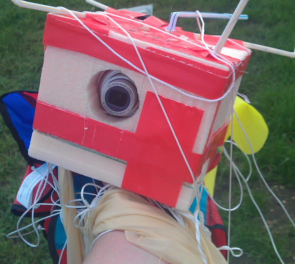
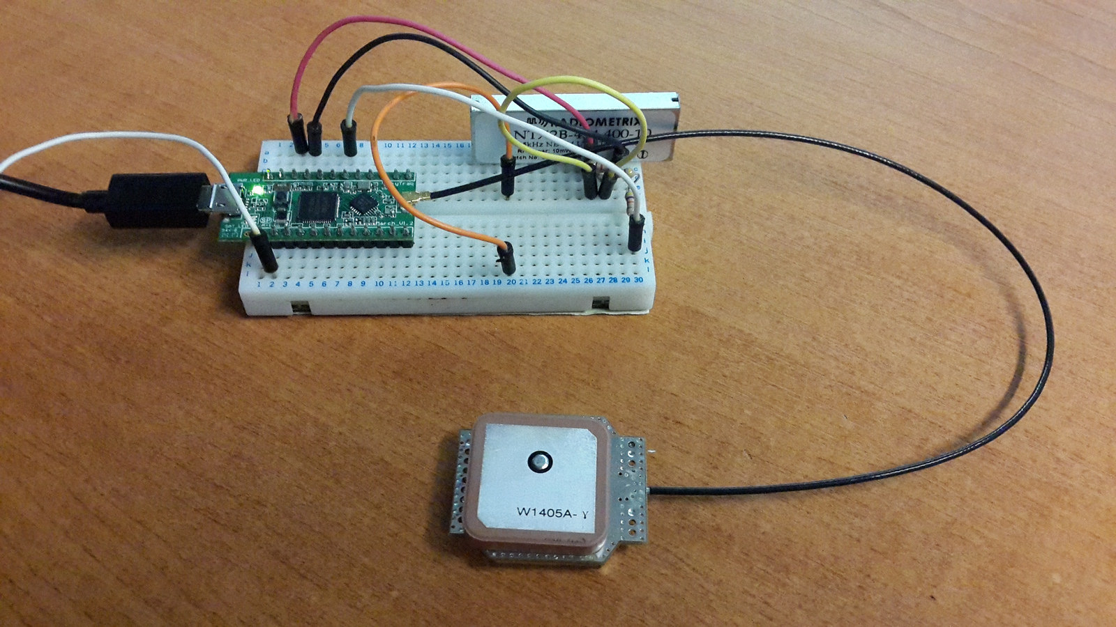
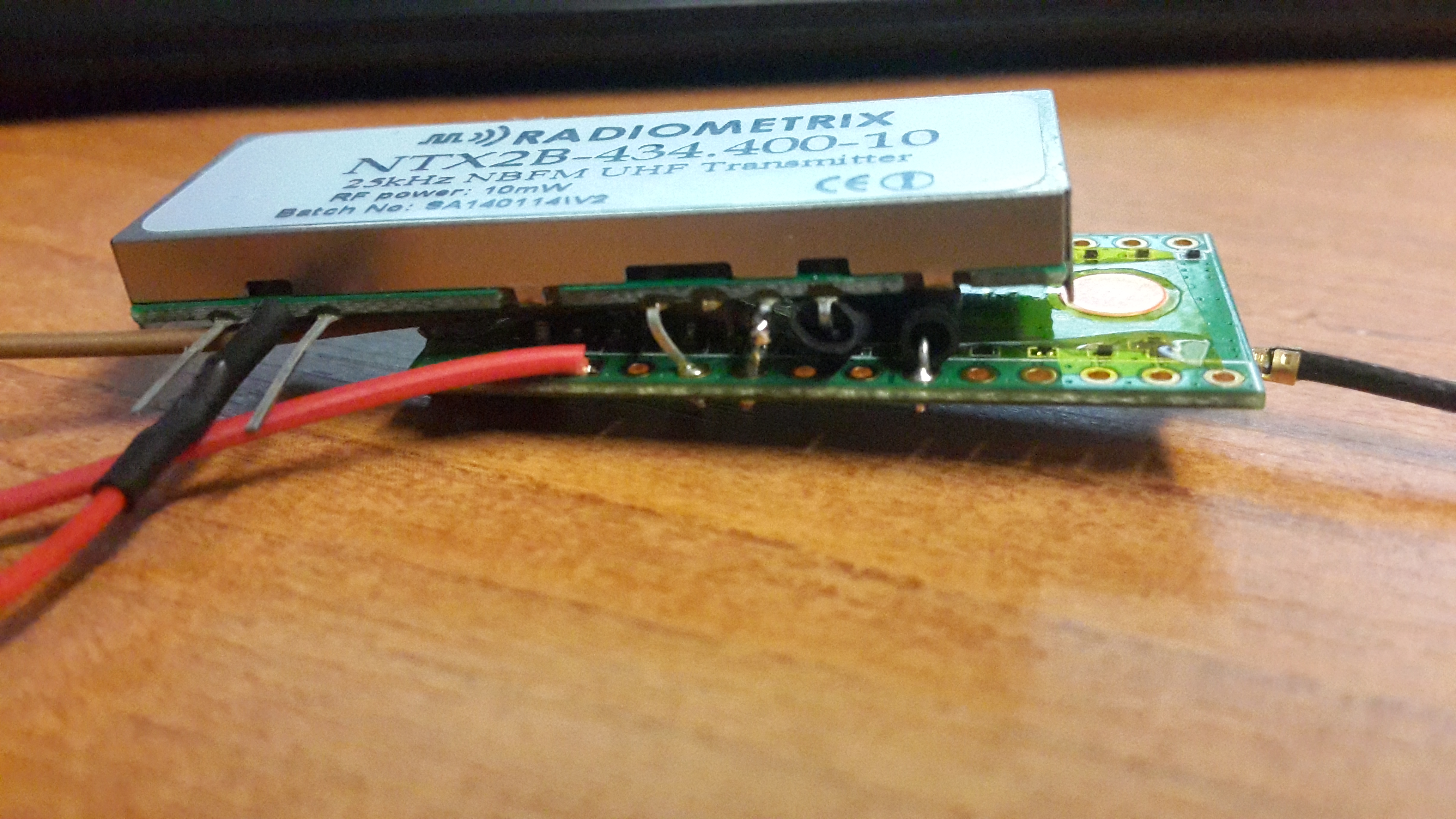
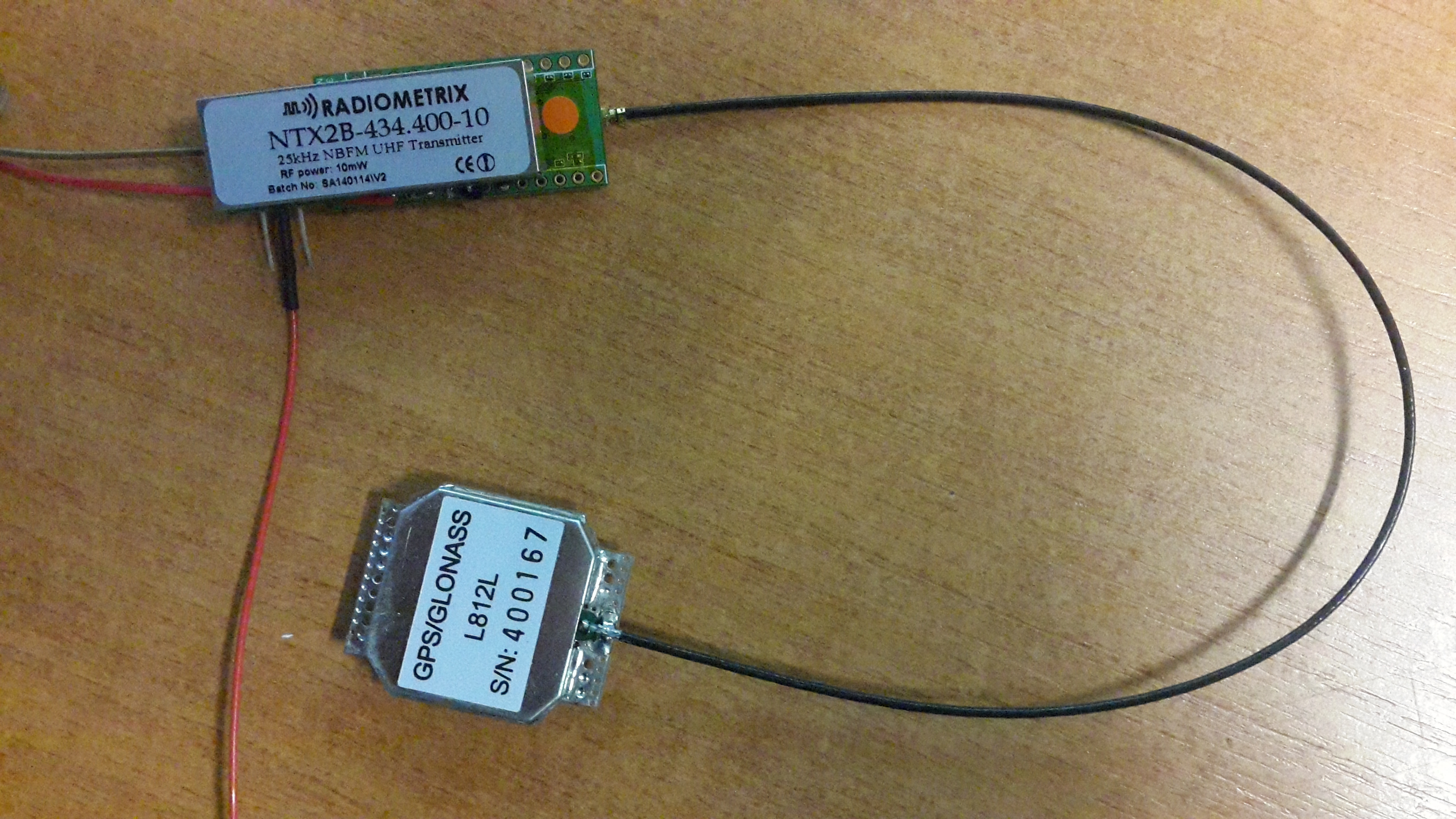
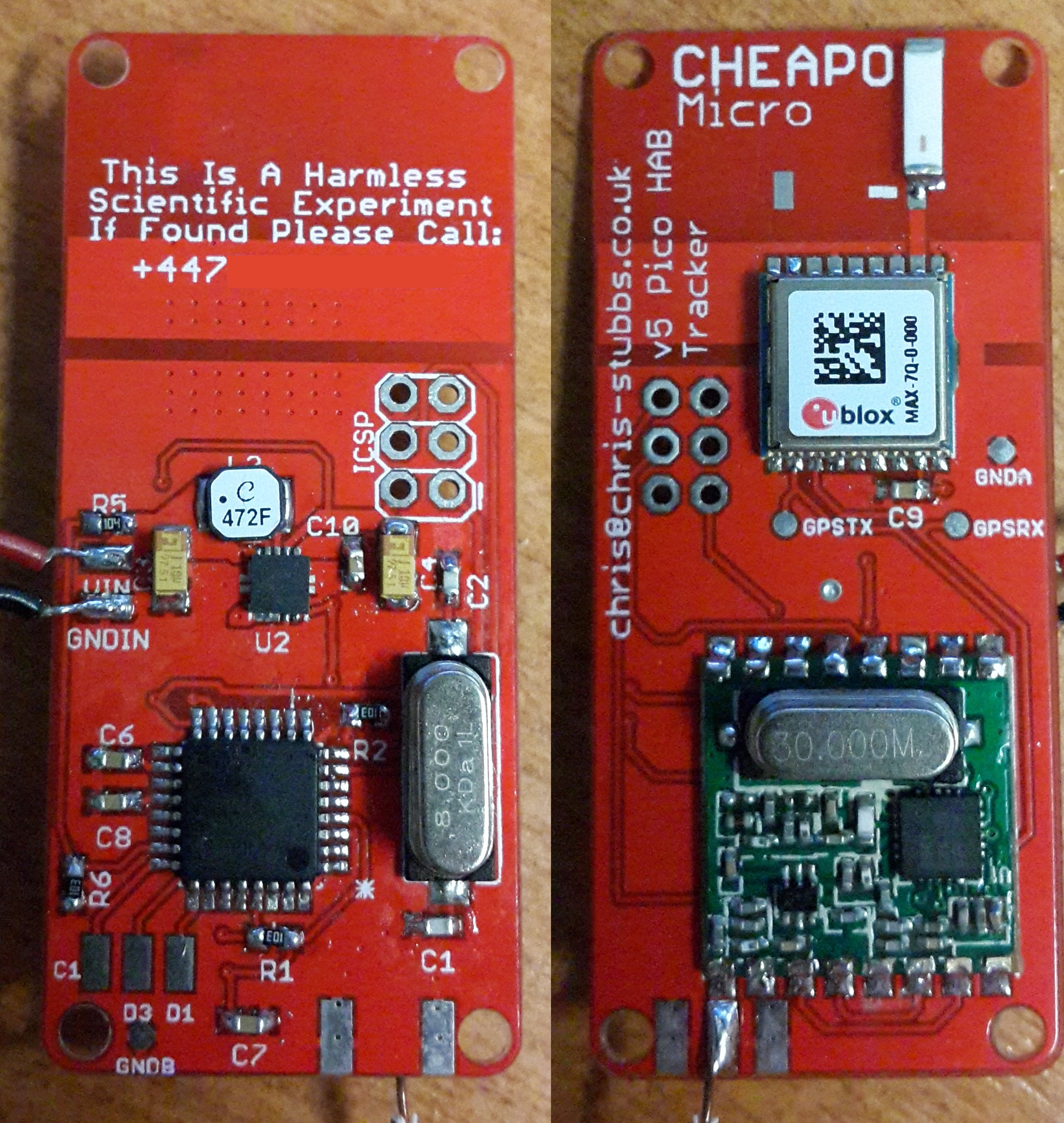
Now the above is pretty neat, but up until starting this project I really underestimated the power of a camera running CHDK! In the article below I will be using a Canon PowerShot A530 to broadcast photographs over a Radiometrix NTX2 FSK radio module, in a similar way Dave Akerman does on his Raspbbery Pi payloads.

8744577917_5038e11e1d_b

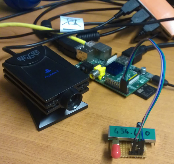
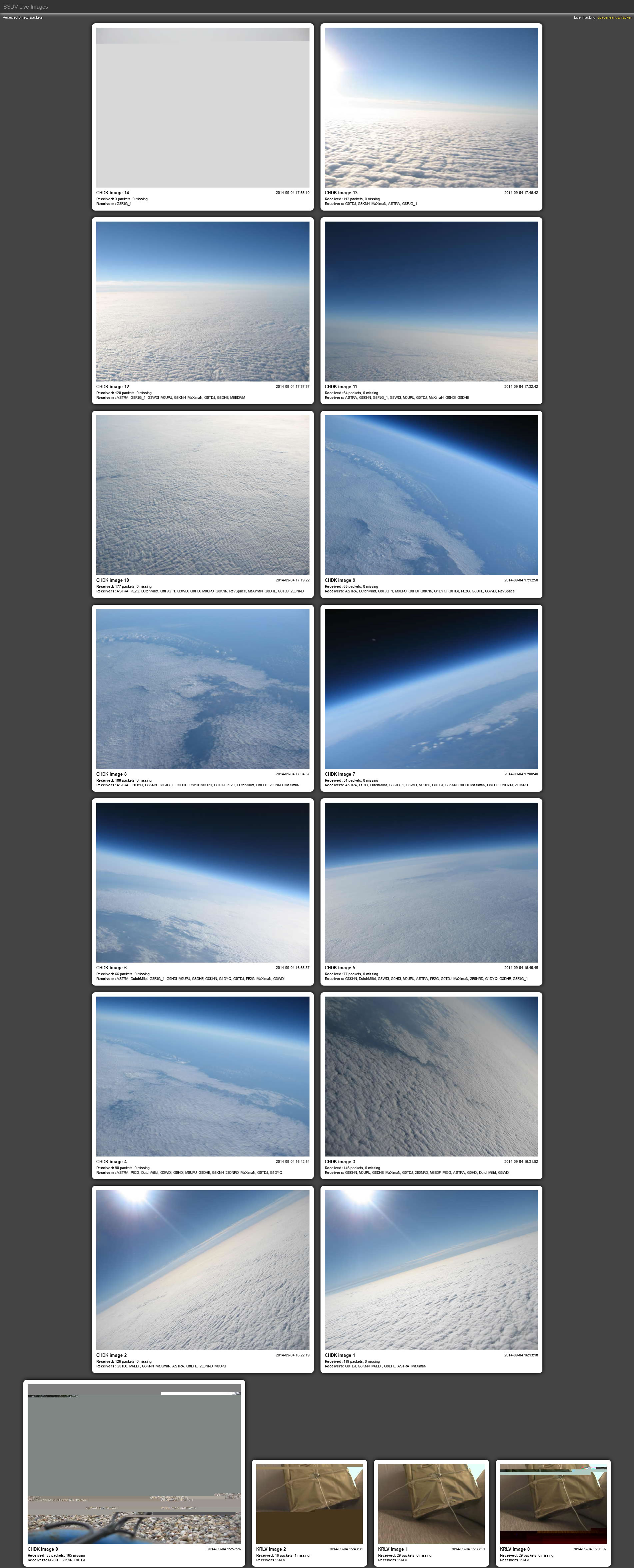
SSDV (Slow Scan Digital Video) is a packetised digital form of SSTV (Slow Scan TeleVision). It can be used to transmit small images along with the regular telemetry transmitted by a payload during flight. Any digital mode that can carry text or data can be used, although the current implementation is limited to 8-bit RTTY (Radio TeleTYpe).

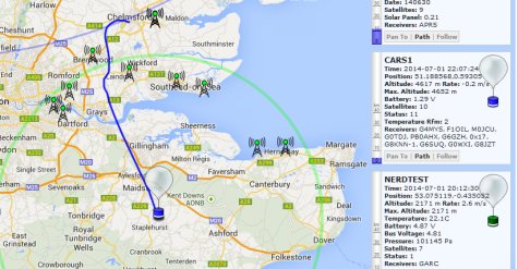
This is a vast improvement over simply sending the JPEG data as it supports forward error correction in the (likley) event that some bits are scrambled in the receiving process. It also supports integration into the UKHAS distributed listener platform, a group of enthusiasts who tune their HAM radios and SDR’s into balloons and upload the data to a central server.

ssdvfldigi

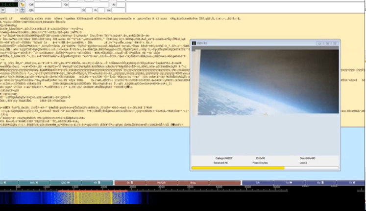
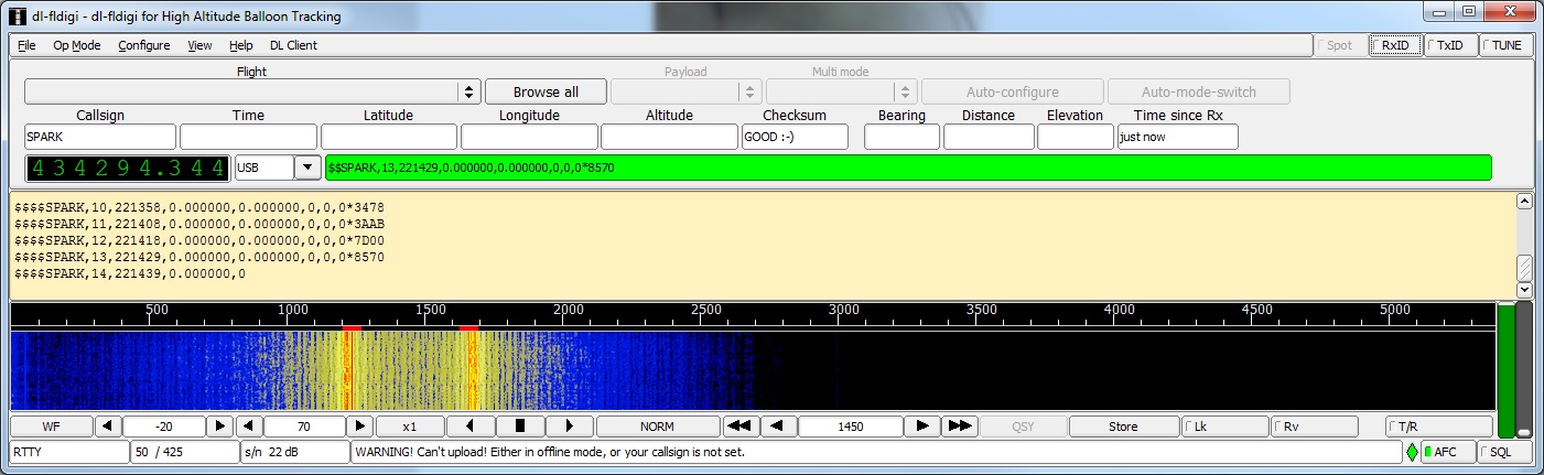
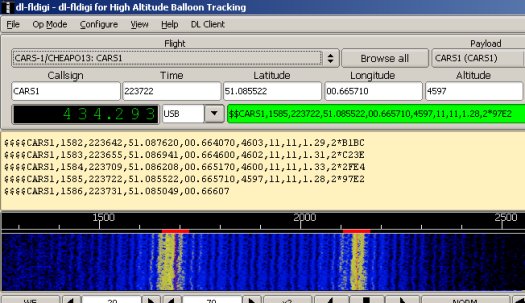
RTTY was originally used on teleprinters in the form of Baudot (5 bit). An RTTY transmitter broadcasts a continuous carrier which shifts up and down in frequency depending on the bit being sent. This produces the MARK (upper) and SPACE (lower) tones. You can see these two tones in the waterfall above). This is known as FSK (frequency shift keying). In this case we will not be using Baudot, instead we will be using 8 bit ASCII with one start and one stop bit to send a byte of SSDV data at a time.

On the CHDK wiki I started to read up on how toggling one of the cameras LEDs can be used to dump the firmware of a camera over serial. So I started off trying to produce RTTY by toggling an LED on and off. Whilst the code behind this worked, the timing was very inconsistent and I struggled to get anything above 33 bits per second. Not ideal for sending images! I figured there must be an alternative.

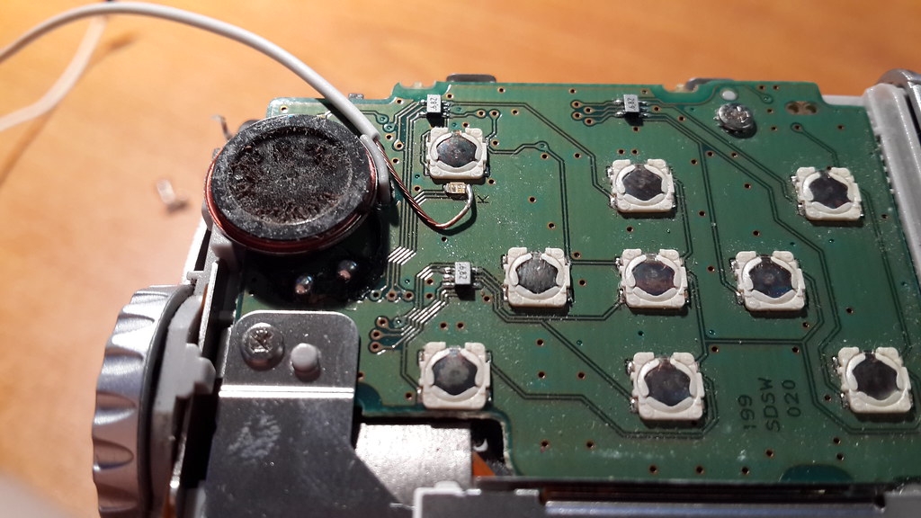
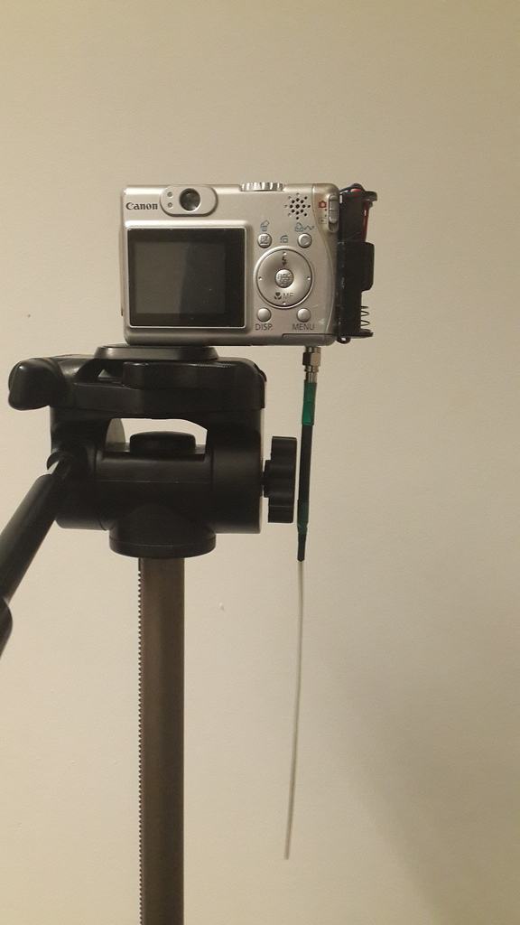
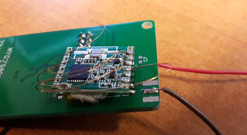
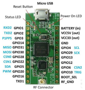
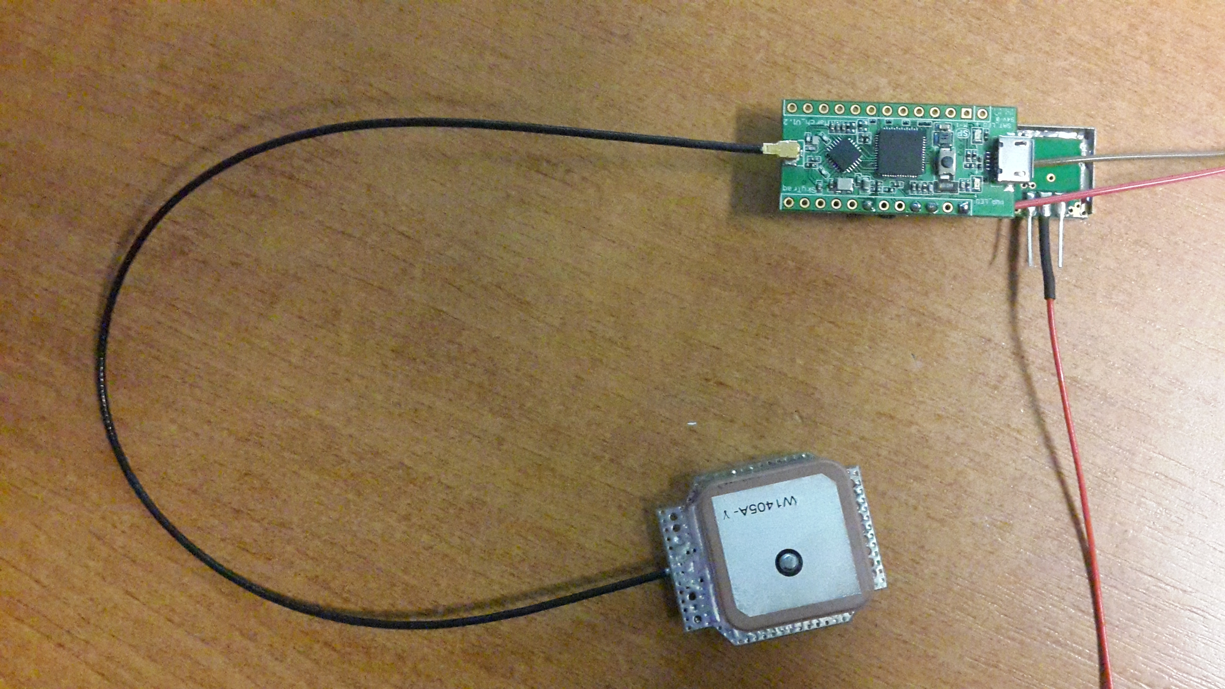
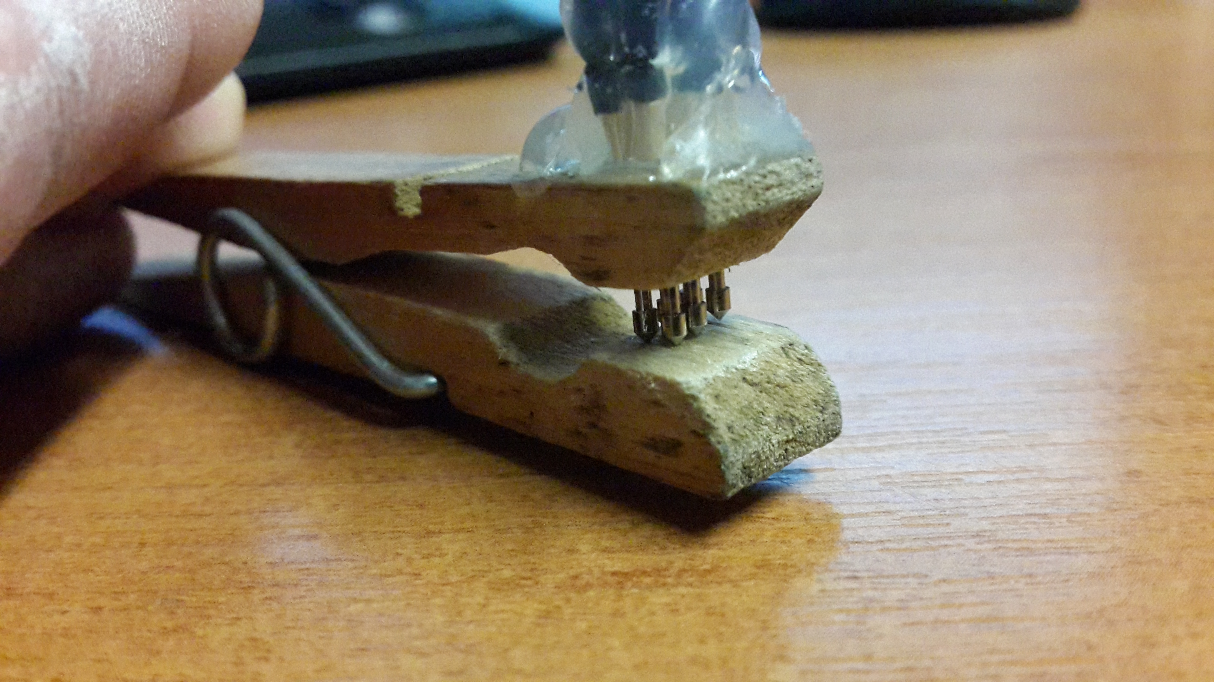
The camera has an ARM processor and runs VxWorks as an operating system, A popular OS for embedded devices ranging from mobile phones to the Mars Curiosity Rover. Using the cameras UART connections it is possible to access the VxWorks event shell and issue basic commands to the camera. The UART connections on the A530 are located under the display and require some fiddly soldering to the unpopulated chip footprint to connect! (Red wire below is the Tx) The UART’s default settings are 115200 baud 8N1.

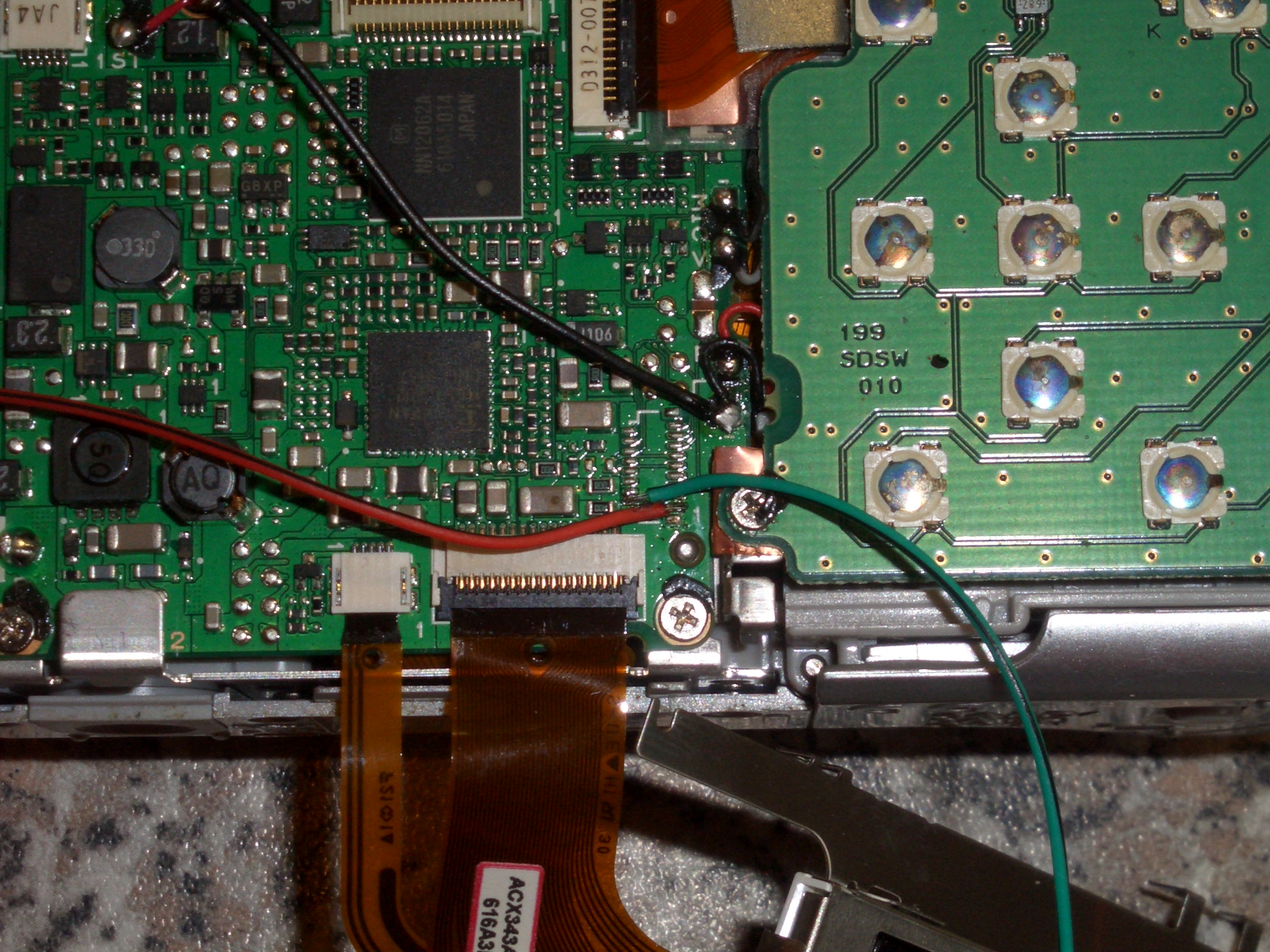
Image from CHDK wiki

Upon experimenting with the UART connected to PuTTY running on my PC, using a USB to TTL converter. I found that the Printf command seemed suitable for writing text to the port. The Printf command is a native call and must be registered by calling SystemEventInit in the VxWorks shell before using it.

To call a native VxWorks function from LUA you must enable native calls in the CHDK menu (ALT, menu, misc, enable lua native calls [check]). Commands can then be executed using event_proc as below.

call_event_proc(“SystemEventInit”)

call_event_proc(‘Printf’,’Script Started’)

To make the UART suitable for RTTY the baud rate will need to be dropped to something a little more sensible, in my testing both 50 baud and 600 baud worked well, however 300 baud seemed to drop characters. Reyalp on the CHDK wiki helped me out by showing me how ioctl() can be used to change the UART settings, and finding the memory addresses for it along with the function codes for some of the commands from VxWorks.

fd=call_func_ptr(0xffec8b34,”/tyCo/0″,0,0) –fptr_open (Opens the UART on fd)
print(“fd:”,fd) –fd>0 if the UART was opened successfuly
status=call_func_ptr(0xffec8630,fd,4,600) –fptr_ioctl(4=FIOBAUDRATE,600=baud)
status=call_func_ptr(0xffec8630,fd,3,0) –FIOSETOPTIONS,3=OPT_RAW,0=OFF (Stops VxWorks messing with null bytes and line returns)
print(“status:”,status) –0 probably means success
call_func_ptr(0xffec84f0,fd) –Closes down fd

The 0xffec8630 function address points to ioctl on the a530, this will probably vary from camera to camera and can be found in stubs_entry.s for your camera in the CHDK source. The function codes for the various icotl commands in VxWorks can then be looked up here [backup: ioLib].

Initially I had a lot of trouble with VxWorks messing with some bytes I was sending to the UART, such as 0x00, and 0x0D being automatically followed by a 0x0A (need to check this). This can be overcome by setting the OPT_RAW option in  FIOSETOPTIONS as above.

I found that printing a whole binary file in one go as a single string did not work, so I use a for loop to print each byte in a string to the UART, rtty being the string name to print below. (note in LUA strings start at character position 1)

for d=1,string.len(rtty),1 do
        call_event_proc(‘Printf’,’%c’,string.byte(rtty,d))
end

Now from this point I could encode a JPEG image to SSDV using Phil Heron’s [fsphil] C based encoder running on a Linux PC. Copyy the files to the SD card,and then read them out to the UART and have dl-fldigi decode them perfectly. The next step is where the real fun started, compiling the C based SSDV encoder into the source of CHDK…


With some more advice from Reyalp at CHDK, Phil and I had a go at setting up the environment required to build CHDK, with myself working on Windows and Phil working on Linux. After a couple of days of Phil installing various bits of Linux software such as GCC, and myself trying to download one of the thousands of CHDK source trunks that would actually build, we managed to succeed at about the same time (For some reason the windows GUI decided to auto-update and started working from that point…). Phil had a go at implementing the C code from his SSDV encoder into the source and we had a semi-working encoder after just one evening! It took a few more revisions of the firmware as we tested different ways of calling the functions and addressing memory.

CHDK build with SSDV for a530 ONLY!

NOTE: I have built the firmware for every platform supported so to download a binary, scroll down…

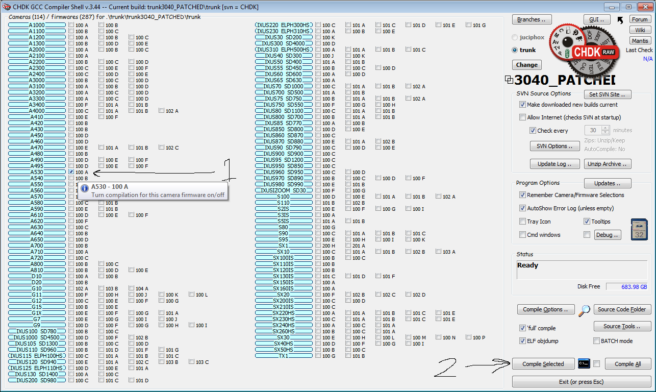
You can use CHDK-Shell GUI under windows to compile the patched trunk for your camera. Or if you are a Linux super genius you can build it using GCC. For windows head to the page linked above. Read it ALL! Download the latest FULL program, run it, enable online mode, let it update, restart. Keep doing the above and eventually you will be up to date enough for it to automatically download the most up to date trunk for you to use.

Change the trunk in CHDK_Shell GUI to the trunk we just patched:selectingtrunk


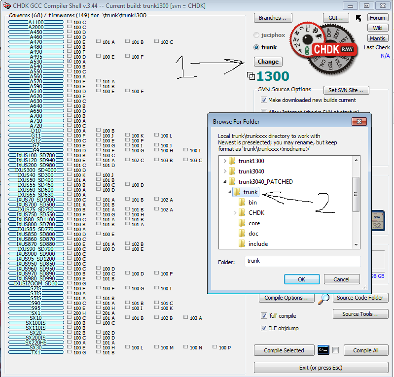
CHDK_Shell should restart and you can tick off your cameras firmware on the list then click “compile selected”select camera and build

Unzip the binaries found in chdk\trunk\trunk3040_PATCHED\trunk\bin (or wherever) to your SD card and boot CHDK, its that easy!

I have had a go at building for every platform available so if you are feeling lazy, give one of these a go. TRUNK3039_SSDV BINARIES DOWNLOAD (Thanks to Dom for hosting the files!)

The first step to encode a JPEG image from LUA is to open the file and read it into memory (JPEG string).

fh=io.open(“A/DCIM/101CANON/filename.jpg”)
jpeg=fh:read(‘*all’)
fh:close()

We now have to create a new encoder object which we can feed the JPEG file into (specifying the callsign as CALL and imageID as 0).

s = ssdvenc.new(“CALL”, 0)

Now we feed the JPEG file (held in the variable we set earlier) into our SSDV encoder object above.

ssdvenc.feed(s,jpeg)

Now we need to enter a loop to make the object encode each packet, checking if the encoding is complete each time so we can jump out of the loop.

i=1 –packet encoder counter
rtty = “” –initialize output string
repeat –start loop
print(“Packet “,i,” encoding”)

–print encoder status message to screen
r, packet = ssdvenc.read(s)

–Read the output packet from the encoder, r being encoder status and packet being 1 SSDV packet.
if r == SSDV_OK then
–If we have data, then do something with it
rtty = rtty .. packet –concatenate new packet onto the end of output stream
i=i+1 –increment packet counter
end
until r ~= SSDV_OK –keep trying to get new packets until the encoder reaches EOF
ssdvenc.close(s) –Close the encoder

So now we have SSDV data in the rtty string. All we have to do is loop through each byte in the string and print it out the the UART

for d=1,string.len(rtty),1 do –loop through each byte
call_event_proc(‘Printf’,’%c’,string.byte(rtty,d))

–print byte to UART as a byte
end

You *should* now have 600 baud SSDV flowing out of your hardware uart and into your ntx2. With a suitable voltage divider you can set the shift to 600Hz and have this decoding in dl-fldigi and uploading to the web!

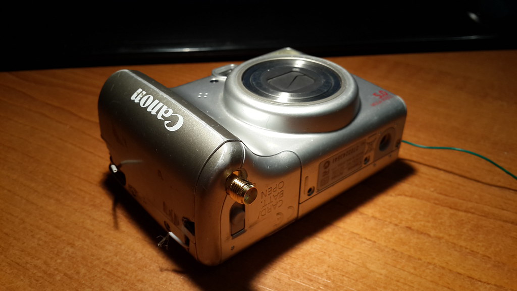
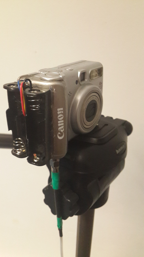
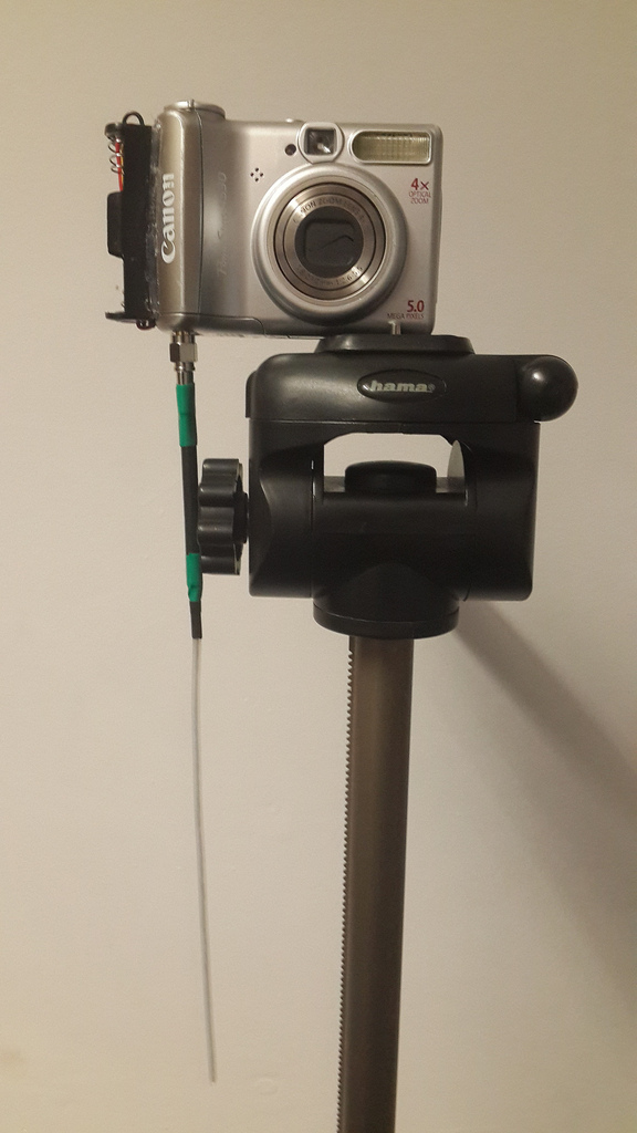
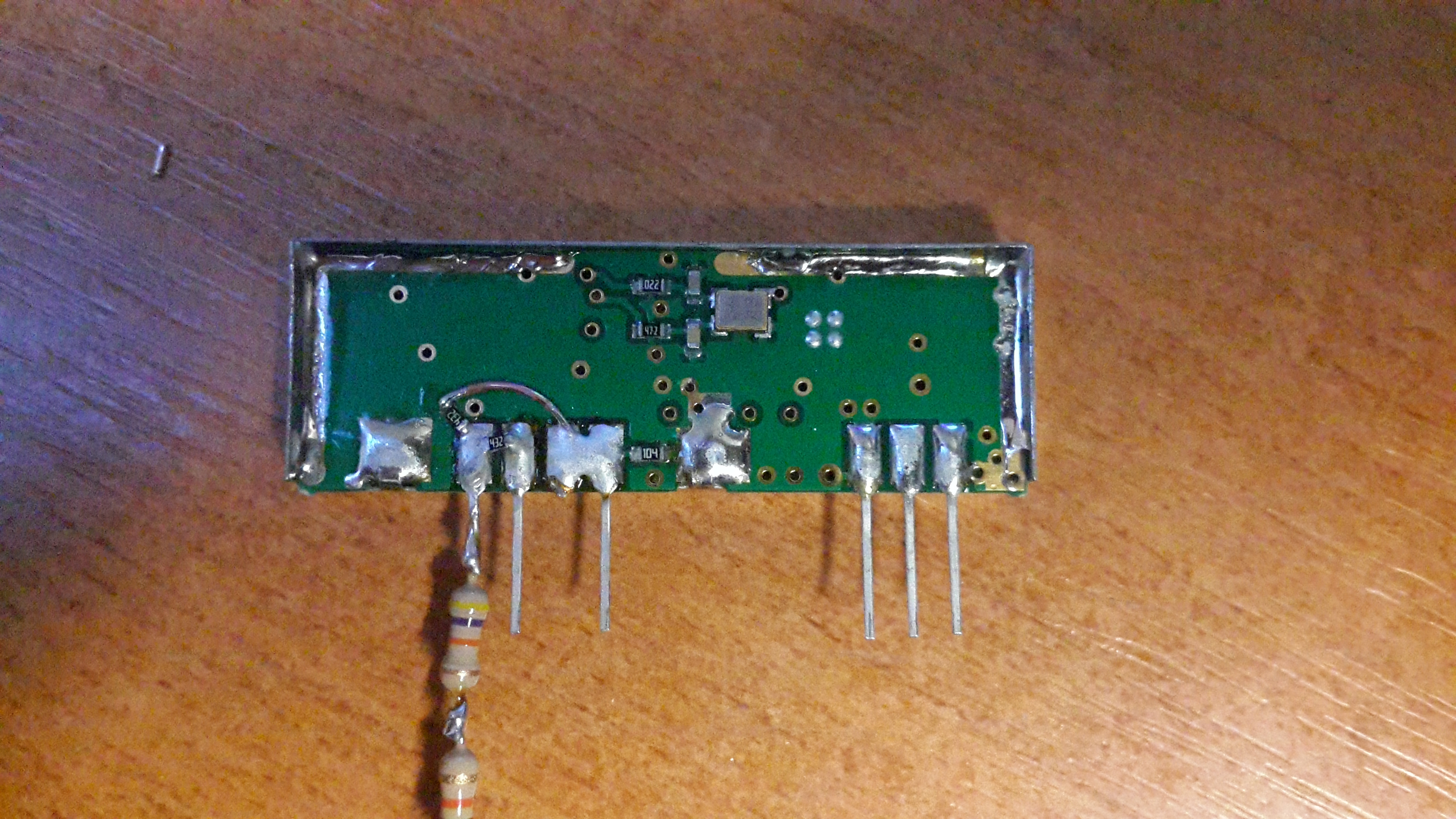
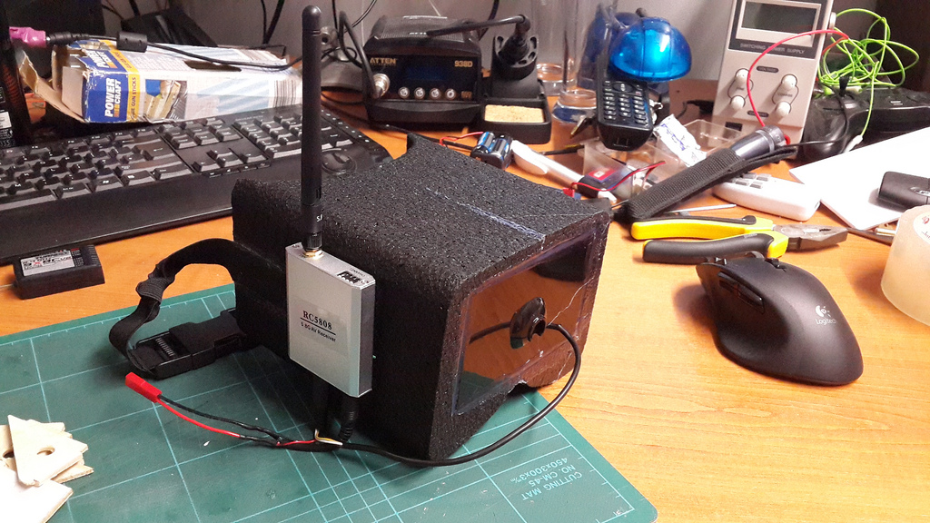
Whilst Phil was compiling the new source, I worked on integrating the transmitter into the camera. The battery bay worked out to be the perfect size, with space for an SMA connector in the battery door!

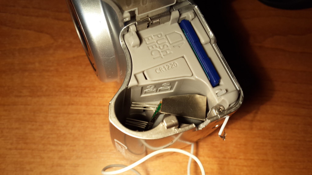
The now out of action battery bay is not a problem, as I wanted to build a 4 cell battery holder to power the camera anyway. This will probably be a 3d printed addition to snap on to the back of the camera or on to the side. As I wanted to demo this at the UKHAS 2013 conference I have added 2 AA holders to the side of the camera just with hot glue for power.

9689914800_0b162f1818_b9689913390_b20bf77351_b9686678691_28c7ea5b6b_b

Demo video of the camera in testing.

People have showed a lot of interest in the project and with a few more tweaks to the code I will be ready to launch it in the next couple of months!

The only thing preventing the camera becoming an entire self contained tracker is the lack of positioning data. I am hoping to be able to get hold of a new canon camera with GPS for geo tagging and send back position reports. I very much doubt canon will have used any specialist GPS chips in the camera to allow it to work above 12km (to comply with US regulations that prevent you using a commercial GPS to build your own cruise missile). I guess the only way to find out is to rip one open! Chances are that whatever GPS module they have used will output serial NMEA data, so a uBlox chip (works to 50km) could quite easily be patched in.

Stay tuned for updates!

CHEAPO7 flight 17/08/2013

I wanted to test the new cheapo4 board at altitude to see how well it worked, but to comply with the <2m rule I could not use a standard 100g balloon (http://randomsolutions.co.uk now stocks a 100g that complies with this rule, which I look forward to testing soon).

After picking up some 36″ party balloons from ebay and testing their burst diameter. I discovered they burst at about 1.2m, well within the limit. The new cheapo4 board was assembled and tested a few days before the flight, and again the night before the flight and worked fine. However once the balloon was filled and the payload attached it refused to get a GPS lock! After hours of moving things around, making sure the battery was out of the way and breaking out the ublox tx pin. I found that it was reporting back 0 satellites with the odd 1 popping up now and again. Not good.

With some more tweaking and still no luck we gave up, but determined to still launch something I pulled out an old cheapo3 board. This too refused to get a fix for some time but eventually came to life. We attached it to the already filled balloon and promptly launched it.

We began the chase , but after what seemed to be no time at all the balloon’s ascent rate started to drop. I thought this could have just been it struggling to break through a layer of cloud but after reaching a grand 813m altitude it started to descend again at about 1.5m/s.

A little disappointing we headed to the landing site and recovered the payload, which was sitting in the middle of a soaking wet corn field (easy recovery none the less).

9592861580_10585d80b3_b 9592864290_8e5f3b975e_b

cheapo7 path cheapo7alt

The cheapo4 tracker seems to have come back to life today, I have no idea what the problem was.. Just hope it doesn’t happen again!

I will certainly try this type of balloon again as I have a few left. It probably just leaked through the neck as I only tied it off with one cable tie. Next time I will consider just sealing the balloon with a conventional knot.

CHEAPO6 foil pico – it floated!

Left this write up a little late… But this was my first successful float! Using a cheapo R3 board powered from a cheap ebay boost regulator. These things are designed for > 0.8v input and 5v regulated output. It turns out by changing a resistor value you can modify them for 3.3v output. These things are not very efficient so only lasted about 8-10 hours.

We filled the 36″ foil balloon carefully using 1.5g of solder to measure the free lift. Which proved to be just about perfect (thanks Leo!). The tracker performed fine (still concerned about the GPS bug before, even though it did not reach 12km) and the balloon floated at a steady 3.7km for 10 hours before the batteries died over the north sea.

cheapo6 path

I have been working on a new tracker PCB which should be smaller, lighter and last longer. Stay tuned for updates!